What Davey did was to make and keep
it accessible to his young readers by
continually adapting it. THE BEGINNER'S 1-VALVER
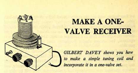
Gilbert Davey would not have claimed any technical novelty for his Beginner's 1-valver - it is simply his version of the well-known leaky-grid-with-reaction arrangement that had been known for years.   What Davey did, as revealed by my trawl through his articles and books, was to make and keep it accessible to his young readers by continually adapting it over a period of no less than thirty years.   The history of this famous and extraordinarily long-lived design is well worth tracing.


Welcome and introduction,
contact details, disclaimer,
rights notice, BVWS link,
site map.
The man who introduced radio
construction to several generations
of boys, many of whom became radio
or communications professionals.
(This page)
The history of the famous
one-valve circuit, 1948-78.
The Studio 'E' 1-valver and
the Focus Transistor radio:
downloads for these famous
designs, and lots more!
This portable receiver clearly became 
very popular, as it was published seven 
times from 1962 to 1981.
A growing resource for those who
built Davey designs years ago, or who
simply wish to know more about them.
Davey sets built by contributors -
including designs that could have been
lost but for some prolonged detective work.
Two home-made coils to use in place of the all-too-scarce
commercial types, suppliers for other components, and
other sources of useful information.
Latest news, links to other sites of interest,
and news archive.
Hover your mouse over the
navigation buttons above for
brief page contents.
Pages marked  >  give access to
one or more subsidiary pages -
see also Site Map at bottom
of WELCOME page.
The various versions of the Beginner's one-valver are described below in order of publication.   In later years, the sequence of versions can be confusing, because new editions of Davey's books appeared in interspersed fashion.   Rights issues may have prompted some of the build variations, and also small variations in the circuit diagram.   However, the main practical reason for revising the design for each edition was the changing availability of components, especially valves and coils.   The successive revisions follow the trend from reliance on home-made coils after the war, through plentiful choice of manufactured coils in the 50s and early 60s, and back to home-made ones in the late 60s and 70s.

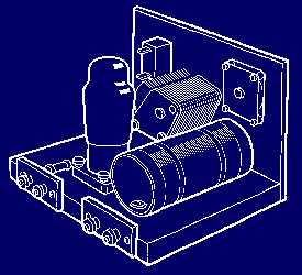
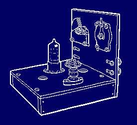
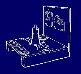
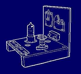
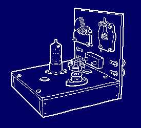
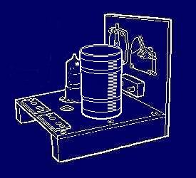
The thumbnail pictorial views on this page have been drawn from the build descriptions.   These views are intended merely to sum up the build arrangement, and are not working drawings.   Some components' shapes are conjectural.

The prototype one-valver had received the 
1947 Test Match broadcasts with sufficient 
strength to drive a small loudspeaker.
    1948:.
    Solid base; HL2K valve; home-made coil.


1948: Boy's Own Paper

As far as I can find, the first version of Gilbert Davey's one-valver was that published in the February 1948 edition of Boy's Own Paper.   "Build a crystal or one-valve radio set" described first a crystal design on a simple solid baseboard chassis and front panel which had enough room to add the valve and associated components.   A home-made coil was described, having aerial and tuner windings, as well as an unused reaction winding ready for conversion to the one-valver.   The reaction capacitor was put in place for use as an optional aerial trimmer.

The one-valve upgrade featured a 2-volt HL2K or similar triode in a surface-mounted valveholder, with its associated components all above the baseboard.

The author reported that using a 25-foot aerial at his home a few miles from the nearest BBC transmitter, the prototype one-valver had received the 1947 Test Match broadcasts with sufficient strength to drive a small loudspeaker.

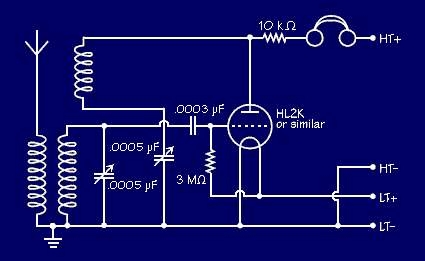
The circuit of the 1948 one-valver,    
with component values.
   

 The circuit was designed around  
the components the young constructor 
was likely to be able to obtain in the 
immediate post-war period.
Only the practical layouts were given, with no "theoretical" circuits.   From the information in the article I have drawn the theoretical circuit as shown, for comparison with the later pentode circuit (see below).   The circuit was designed around the components the young constructor was likely to be able to obtain in the immediate post-war period.

It is worth noting that unlike many one-valve circuits of the period, no HF choke was specified - just a 10kΩ resistor in series with the phones.   Tuning and reaction capacitors were both specified as .0005μF. (1)

For an interesting retro variation on this one-valver using a later Davey coil, see YOUR DAVEY SETS, item 1.   (The following November's edition gave details for adding a second valve; see the same page, item 15, for a receiver built according closely to these instructions.)

1957:    
Raised baseboard; DAF91 valve;    
Teletron D/R coil.
   

The B7G valveholder required a through hole 
mounting, so a simple solid baseboard would 
not do.
1957: Fun with Radio, 1st edition

After the 1948 version as above, I have been unable to find a subsequent appearance of the Davey one-valver in the Boy's Own Paper backnumbers, or its offshoot publications, until 1961 (see later).   However, the design must have been revised as below some time before 1957, and may have appeared as a separate BOP supplement which interested readers could send for.   If you can confirm the existence of such a supplement, I would be grateful if you would CONTACT ME.

Be that as it may, the "Beginner's One-Valve Set" included (with other popular BOP designs) in Gilbert Davey's first book, Fun with Radio, published in October 1957, is clearly descended from the 1948 design.

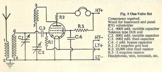
The circuit was revised to use a 1.4 volt pentode (DAF91) of the type which became readily available chiefly for use in portable radios.   The B7G valveholder required a through hole mounting, so a simple solid baseboard would not do.   A wood chassis in the form of an inverted tray was suggested, with the front panel fixed to one edge. (2)

The one-valver circuit and    
components list from    
Fun with Radio, 1st edition, 1957.
   

Drawn by R Barnard Way; reproduced    
with acknowledgments to R Lawrence.    
Other rights may subsist.    
Image from site author's copy.    


These valves incorporated a screen grid, 
so appropriate components were added 
(R3 and C4 in this diagram).
Using these miniature valves meant that a 2-volt accumulator was no longer needed, and dry-cell batteries could be used for both HT and LT.   These valves incorporated a screen grid, so appropriate components were added (R3 and C4 in this diagram).

By the mid-50s, several firms were producing ready-made coils suitable for simple receivers, and instead of a home-made coil, the Teletron D/R coil was specified.   This had aerial, grid (medium wave) and reaction windings.

1957:    
The Studio ‘E’ one-valver    
according to the BBC leaflet.
   

The useful split-floor chassis idea may 
have been adapted from a design for 
a short-wave one-valver . . .
1957: The Studio ‘E’ set

With the Studio ‘E’ leaflet to hand, we can re-assess its place in the sequence of Davey one-valvers.   I have re-drawn my thumbnail view to accord with the leaflet - see The Studio ‘E’ Leaflet. (3)   Also on that page is an image from a Fun with Radio dust jacket showing a Studio ‘E’ prototype set.

We know a little more about this set following discovery of the series of letters in Wireless World - see Studio ‘E’ under fire!

The theoretical circuit is the same as that which appeared in Fun with Radio, first edition, with the same coil (Teletron D/R), and variable capacitors (.0005μF/500pF tuning; .0001μF/100pF reaction).   Fixed capacitors are the same, but R2 and R3 (anode and screen grid resistors) are lowered somewhat, perhaps to ensure adequate reaction with the 69 volts HT supplied by the specified combined HT/LT battery.   For the valve, DAF91 or DAF96 are given as alternatives.

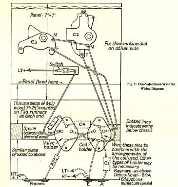
I previously speculated that the split-floor chassis idea had been adapted for the Studio ‘E’ from the short-wave receiver that appears on page 59 of Fun with Radio, first edition.   This feature would have contributed towards ease of construction for the many first-time builders who followed the Studio ‘E’ series.

The short-wave one-valver, with    
split-floor chassis, from    
Fun with Radio, 1st edition, 1957.
   

Drawn by R Barnard Way; reproduced    
with acknowledgments to R Lawrence.    
Other rights may subsist.    
Image from site author's copy.    


Was this the set that inspired
the Studio 'E' design?
Now that the leaflet is to hand, this guess is still more tempting, as it can be seen that the component layouts of the two sets are strikingly similar.   See page 3 of the leaflet here, then use your browser's "Back" button to return to this page.

Both designs mount the valve dead centre on the slot, and both place the coil to its left as seen from the front.   The tuning and reaction capacitors are disposed the same way - tuning on the left, reaction on the right (again as seen from the front).   Finally, the aerial, earth and phones terminals occupy the same positions across the back of the chassis.   However, the different valve and coil types used in each set mean that the point-to-point wiring differs quite a lot between the two.

A simple medium-wave TRF set like the Beginner's One-valver is quite uncritical in layout.   It seems likely that Gilbert Davey simply reproduced both the slotted chassis and component arrangement from the short-wave set, then "joined the dots" to suit the components of the Studio ‘E’ set.   But why leave so much space at one side?   Was it so as to leave room for adding a second valve and associated components, as indeed I did to my first set?   Perhaps he simply felt that the most important component of a one-valver should occupy "centre-stage".

1959 - 1961: Fun with Radio, 2nd and 3rd editions

The second (1959) edition of Fun with Radio is missing from the British Library collection, but recent purchase of a copy allows me to confirm that the beginner's one-valver appears exactly as in the first edition. (4)

I have not yet been able to inspect the third (1961) edition (it is also missing from the British Library collection), but Doug Brown has kindly confirmed by enquiry that this edition carries the beginner's one-valver chapter unchanged. (5)

1962: Boy's Own Companion No.4   
Metal-chassis one-valver    
with home-made coil; title picture.    

Copyright © Lutterworth Press;    
reproduced by kind permission.    
British Library image; Copyright ©    
British Library Board: Shelfmark 12841.gg.23.    


A home-made coil . . . together with the valve, 
were displayed proudly on the top face of the chassis.
1961: Boy's Own Paper

The June 1961 BOP carried a most elegant one-valver version, built into a metal chassis with flanges tall enough for the front flange to house all the controls and thus serve as the front panel.

The set used a home-made coil with aerial, medium-wave, long-wave and reaction windings (described in the January 1961 BOP).

This, together with the valve, was displayed proudly on the top face of the chassis.   The valve was specified as 1T4 or DF91, with the layout showing pin connections to suit.

There were two errors in this article: the screen grid resistor was shown connected to the anode side of the phones, rather than direct to HT+ve, and the circuit diagram omitted the connection from HT-ve to LT-ve.   For corrections, see the circuit diagram included with the Davey coil download on the CONSTRUCTION RESOURCES page.

The article was reprinted in the 1962 Boy’s Own Companion No.4, unfortunately with the same errors. (6)   In both publications, the circuit diagram showed the reaction coil and capacitor below the ground line, possibly to ring the changes for rights reasons.

My version of the 1961-2    
one-valver, with aluminium chassis    
and Tufnol front and rear panels.
   

My version of the 1961-2 one-valver.
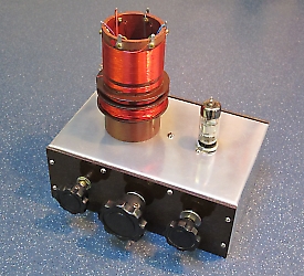
Recently I found time to build my own version of this attractive set.   Some time ago, Hugh Castellan, several of whose Davey sets feature on this site, very kindly made for me a beautiful example of the long- and medium-wave coil that Davey featured in this design.   (Please see the CONSTRUCTION RESOURCES page for the download with instructions for making this coil.)

(My chassis is of folded aluminium sheet for the top and sides, with front and rear panels of 3mm Tufnol.   The control on the left is a 3-position rotary switch that combines wavechange with a central "off" position, interrupting the LT supply.   I found that on long wave, a .0001µF capacitor did not give enough reaction, so I used .0005µF capacitors for both tuning and reaction.)

1962:    
Baseboard on side runners, DF91 or    
DF96 valve, Teletron D/R coil.
   

A chassis arrangement owing something 
to the Studio ‘E’ build . . .
1962: Fun with Electronics, 1st edition

A chassis arrangement owing something to the Studio ‘E’ build was adopted for Fun with Electronics (1962).   The baseboard was shown supported on side runners (but is not split transversely), and paired sockets were shown at the rear of the baseboard.   The valve was specified as DF91 or DF96, and the Teletron D/R coil was used again.   The layout placed the tuning capacitor on the same side as the coil (left side), and the reaction capacitor on the valve's side.   An on-off switch was included in the LT+ve supply. (7)

The circuit diagram was re-drawn for Fun with Electronics, possibly again for rights reasons.   Some lines are dog-legged, and the reaction circuit is shown leading to ground between the aerial and grid coils.   The screen grid components repeated the arrangement used in the metal-chassis 1961 design (above).

1965-69:    
Revised to use Repanco coil,    
and wavechange switch.
   

By . . . 1965, the Teletron coil had 
evidently become hard to buy . . .
1965-69: Fun with Radio, 4th & 5th editions

By the fourth edition (1965), the Teletron coil had evidently become hard to buy, as we find the practical layout altered to show the Repanco DRR2 coil (the theoretical circuit diagram was unaltered since the first edition and still showed the connections for the Teletron coil).   The Repanco coil had medium and long-wave windings (necessitating a wavechange switch) and a reaction winding, but no aerial winding.

The dust-jacket of the fourth edition includes a picture of the Studio ‘E’ one-valver, although this is not the version featured in the book.

The fifth edition of Fun with Radio (1969) repeated this one-valver version exactly. (8)

1972:    
Home-made coil re-introduced as    
commercial supplies dwindled.
   

By 1972, manufacturers were moving away 
from coils suitable for simple sets . . .
1972: Fun with Electronics, 2nd edition

By 1972, manufacturers were moving away from coils suitable for simple sets, and the Teletron D/R coil was out of production. The Fun with Electronics chapter was revised to give the choice of either the Repanco DRR2 coil (wavechange switch required), or a home-made coil with aerial, grid (medium-wave) and reaction windings, as shown in the thumbnail.   The on-off switch was still shown, so sets built to this design might have had one or two switches on the front panel, depending on the coil used. (9)

See YOUR DAVEY SETS for a recently-built example of this version.

1978:    
With the home-made long-    
and medium-wave coil.
   

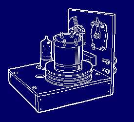
It would have been necessary to place the valve 
well to one side of the chassis in order to 
accommodate this large-diameter coil.
1978: Fun with Radio, 6th edition

By 1978 (Fun with Radio, 6th edition), the Repanco coil was still available and was still shown in the one-valver layout.   The book's theoretical circuit was finally updated to show the Repanco coil as well.   A refinement was added to the circuit in the form of a .001μF capacitor across the headphone terminals, presumably as a tone-control element.

The trend away from manufacture of coils for simple sets continued, and this edition therefore included a chapter on home-made coils.   Details were given of the dual-waveband home-made coil originally published in the January 1961 BOP. (10)

The chassis build shown was as in previous Fun with Radio editions.   My thumbnail drawing shows this chassis with the home-made coil. It would have been necessary to place the valve well to one side of the chassis in order to accommodate this large-diameter coil.

BACK TO TOP
CONTACT ME
As far as I know, the sixth edition of Fun with Radio was the last to be published in the UK.   Editions often seen identified as published in 1986 in the USA by Sportshelf & Soccer Associates are UK editions imported for sale there.


(1) Boy’s Own Paper, Lutterworth Periodicals, February 1948, pp18-20.
(2) Fun with Radio, Gilbert Davey, Edmund Ward Ltd, 1957, pp16-18.
(3) Making Your Own Radio Set, BBC, September 1957 (the Studio ‘E’ leaflet).
(4) Fun with Radio, Gilbert Davey, 2nd edition, Edmund Ward Ltd, 1959, pp19-21.
(5) Fun with Radio, Gilbert Davey, 3rd edition, Edmund Ward Ltd, 1961, pp19-21.
      details forwarded by Doug Brown, May 2011.
(6) Boy’s Own Paper, Lutterworth Periodicals, June 1961, p61.
      reprinted in Boy’s Own Companion, Vol 4, Lutterworth Press, 1962, p100.
(7) Fun with Electronics, Gilbert Davey, Edmund Ward Ltd, 1962, pp13-17.
(8) Fun with Radio, Gilbert Davey, 4th edition, Edmund Ward Ltd, 1965, pp14-16.
      and 5th edition, Kaye & Ward Ltd, 1969, pp16-18.
(9) Fun with Electronics, Gilbert Davey, 2nd edition, Kaye & Ward Ltd, 1972, pp15-20.
(10) Fun with Radio, Gilbert Davey, 6th edition, Kaye & Ward Ltd, 1978, pp25-28.