|

|

|

|

|

|

|

|

|

|

|

|

|

|

|

|
Hover your mouse over the
navigation buttons above for
brief page contents.
Pages marked > give access to
one or more subsidiary pages -
see also Site Map at bottom
of WELCOME page.
|
|
|
The salesman was somewhat patronising, going through each component's
characteristics and purpose in unnecessary detail. My mother, a State
Registered Nurse, said indignantly: "Never mind how his radios ticked -
I could have told him how he ticked!".
|
|
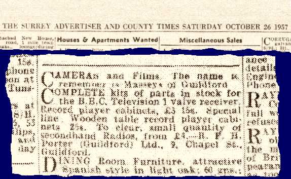
Surrey Advertiser, October 26, 1957, with R F H Porter's
small-ad offering kits for the BBC one-valve receiver.
Copyright © Surrey & Berkshire Media Ltd;
reproduced by kind permission.
Prepared from a British Library image, copyright © British Library
Board: Shelfmark 476.
|
I didn't really know how radios ticked either, and the leaflet didn't mean much to
me. However, I noted the confident assertion at the end of the instructions
on page 2: "Insert valve, connect aerial, earth, phones, battery; set now works".
To this I added in a childish hand "WE HOPE!!!", summing up both my
anticipation and perhaps a healthy scepticism at such confidence.
My Dad set to work and first built the chassis, not of plywood as many doubtless
were, but of glossy brown Paxolin. This, set off by a couple of pierced
aluminium brackets bracing the front panel, lent the whole thing a high-tech
scientific aura that had great appeal for his 10-year-old client!
Dad was an engineer who had started his working life as a plumber's mate, and
was expert at soldering - the plumber's way. He didnĺt have an electric
soldering iron, or cored solder. He sat in his favourite chair by the fire,
in which the soldering iron was heated. You knew when it was hot enough by
the eerie green flame that surrounded the copper bit. The bit was first
dipped with a hiss into Baker's Soldering Fluid, then a stick of tinman's solder
was applied to it. The iron was brought to the joint to be soldered (which
already had a drop of Baker's Fluid applied), there was another hiss, and the
joint was made. (You can still get Baker's Soldering Fluid -
it now comes in a plastic container, so it doesn't eat its way out as it did from
the old metal can!)
As an afterthought, my father added a switch in the LT supply after consulting
a knowledgeable relative as to whether this would also cut off the HT current.
It only remained to rig up an aerial in the loft, run an earth wire behind the
chest of drawers to the existing earth connection on my brother's crystal set,
and deliver a careful warning to me about interfering with nearby listeners'
reception with improper use of the reaction control.
Mostly I listened to Radio Luxembourg, learning (along with the rest of my
generation) how to spell K-E-Y-N-S-H-A-M, but I also remember listening to a
Home Service drama series of "Lorna Doone", and a Children's Hour
programme about the life of the civil engineer I K Brunel on the centenary
of his death (1959).
By this time, I had moved to secondary school (Sheerwater County Secondary,
Woking, now Bishop David Brown School), and waited impatiently to join the
Science Club, only open to Third Year pupils and above. My first project
here was to add another valve to the one-valver to drive a loudspeaker (this
would have been autumn 1960). I was assisted in this by the exceptional
teacher who presided over the Science Club, Mr King.
E V King was a prolific writer for Practical Wireless and other titles,
so much so that he acquired two pen-names: G K Vine and K Given (anagrams of his
name). His school lab was stuffed with Government-surplus equipment and
components of all kinds. It seemed you could build anything there.
It was my idea of Heaven.
From this treasure-house came the necessary parts to add another valve,
including the valve itself, an LF transformer, an output transformer and a
loudspeaker. Having learned how to solder the radio engineer's way,
I built most of the extra components on to the one-valve chassis itself.
I'm fairly sure that I had kept my BBC leaflet at least to this point, and that
I worked from Mr King's sketched additions to the leaflet's original circuit
diagram. (To support the second valve and the inter-stage transformer, I
fixed a piece of wood to the right-hand aluminium bracket, drilling a hole in it
for this purpose. (These same brackets have gone into my rebuilt set, and
that hole can still be seen - see My Rebuilt
Studio ‘E’ Set.)
I made up a plywood cabinet to house the chassis, speaker, output
transformer and battery. I got into a bit of trouble at home because I
used some wood bought for another purpose, but both my parents agreed that I
had made a good job of it, and my mother found a piece of fabric to cover
the speaker aperture.
By this time, transistors were becoming readily available, and Science Club members
built transistor radios to Mr King's duplicated plans. More advanced Science
Club members were still building multi-stage valve receivers to his designs.
|