I had devised a practical layout that
I thought must be close to the original. My Rebuilt Studio ‘E’ Set
In 2009, before the BBC Studio ‘E’ leaflet was rediscovered, I built a "conjectural" Studio ‘E’ one-valver, based on my memory of the set my father built for me in 1957, and incorporating the parts I had kept for all those years.   I had followed the almost identical circuit in Gilbert Davey’s Fun with Radio (1st edition, 1957), and had devised a practical layout that I thought must be close to the original.   This page carried details of that set since the site was launched in 2010, but it now describes my second rebuild, completed during May 2012.


Welcome and introduction,
contact details, disclaimer,
rights notice, BVWS link,
site map.
The man who introduced radio
construction to several generations
of boys, many of whom became radio
or communications professionals.
The history of the famous
one-valve circuit, 1948-78.
The Studio 'E' 1-valver and
the Focus Transistor radio:
downloads for these famous
designs, and lots more!
Undiluted nostalgia - memories of
my original Studio ‘E’ 1-valve set.
(This page)
Details and pictures of my Studio ‘E’
set, now rebuilt (for the second time!)
largely according to the leaflet.
Comments on the 1957 leaflet and on
the design itself. Image downloads - please
read copyright and usage notes.
Extracts from the scripts preserved by
Gilbert Davey himself since the one-valver
series was broadcast in 1957.
A series of letters to Wireless World
in which Davey defends the Studio 'E' design.
This series raised almost as much interest as
the earlier one-valver series. Some stories by
those who remember the series. Notes on the
leaflet and the design.   Image downloads -
please read copyright and usage notes.
My recently built version of this simple set
This portable receiver clearly became 
very popular, as it was published seven 
times from 1962 to 1981.
A growing resource for those who
built Davey designs years ago, or who
simply wish to know more about them.
Davey sets built by contributors -
including designs that could have been
lost but for some prolonged detective work.
Two home-made coils to use in place of the all-too-scarce
commercial types, suppliers for other components, and
other sources of useful information.
Latest news, links to other sites of interest,
and news archive.
Hover your mouse over the
navigation buttons above for
brief page contents.
Pages marked  >  give access to
one or more subsidiary pages -
see also Site Map at bottom
of WELCOME page.
My new rebuild is generally much more in
accordance with the leaflet, but still seeks
to capture the spirit of the set my father
built for me in 1957, with his departures
from the published design.
    My second rebuild of the Studio ‘E’ set, completed May 2012.


When the leaflet came to light, it emerged that my “conjectural” set was correct in its front panel layout (tuning capacitor on the left, reaction on the right), but that I had reversed the positions of the valve and coil.   (This arrangement had been decided upon for what seemed to be the best of reasons at the time, and indeed gave rise to a very satisfactory wiring layout.)   It also turned out that the chassis for this set was a good deal bigger in all three directions than it should have been.

My new rebuild is generally much more in accordance with the leaflet, but still seeks to capture the spirit of the set my father built for me in 1957, with his departures from the published design, which I point out in the following notes.   See also My Original Studio ‘E’ Set.

The completed chassis, now a    
good deal smaller than before.    

Clearly visible (arrowed) is the hole drilled
in the further bracket when I later added
a second valve to the original set.
Chassis

Use of the aluminium side brackets from the original 1957 set means that the front floor panel has to be a little deeper than the 2” specified by the leaflet, so that it can have holes in it corresponding with the middle fixing holes in the brackets.   When building the original 1957 set, my father would have had to increase this depth for the same reason.   Clearly visible (arrowed) is the hole drilled in the further bracket when I later added a second valve and associated components to the original set.

For this second rebuild, I found a piece of genuine Paxolin just big enough to cut out some new floor panels, so these have gone into the new rebuild for old time's sake.

The rear floor panel didn’t have to be the same size as the front one, but I elected to make the two panels the same size for the sake of appearance.   Leaving a 9/16” slot to suit my valveholder (avoiding the need to notch the panel edges) brings my chassis to 4 15/16” deep excluding the front panel (leaflet shows 4 1/2”)

For the front panel of the original set, my father probably stuck to the size specified by the leaflet, but the tight space between the variable capacitors and the floor panel gave him trouble when adding the on-off switch as an afterthought - it ended up off-centre.   I have re-used the Tufnol front panel from the "conjectural" set (with its symmetrically arranged variable capacitors and switch), but have cut it down to 4 3/4” by 4 1/4” - just 1/4" oversize in height and width.

So my new chassis is now considerably smaller, and quite close to what the leaflet specifies.

Each panel was cut approximately 2mm oversize, then brought to exact size and squareness with a sharp block plane to avoid chipped edges.   The slightly "brushed" finish of the Tufnol front panel had already been glossed up with Brasso wadding during the building of the "conjectural" set, and the appearance of the Paxolin for the floor panels was improved by carefully sanding out some scratches with fine "wet and dry" paper used dry, and polishing with Brasso wadding.   The Tufnol and Paxolin panels are a quite good colour match.

The side runners are beech, planed and sanded, treated with one coat of clear polyurethane varnish, flatted off with "wet and dry" paper used dry, then wax polished.   The chassis is assembled with brass wood screws (3/4" x no. 6 c/sk), and brass bolts (6BA x 1/4" c/sk) and nuts.

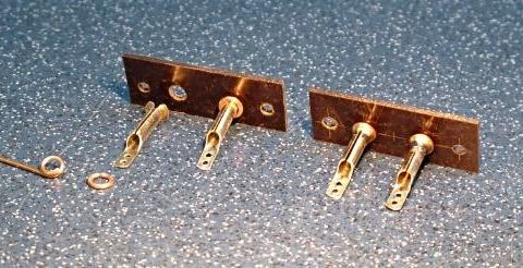
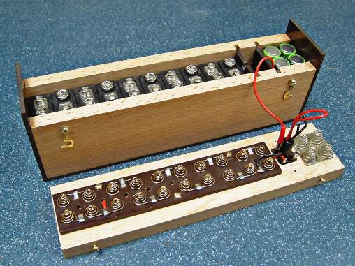
Home-made wander socket strips.    
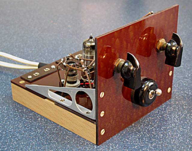
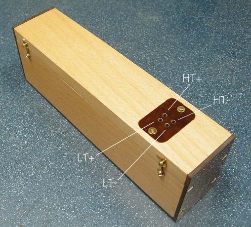
These once-common items
seem hard to find now.
Wander sockets

These once-common items seem hard to find now.   The ones I made for my "conjectural" set were too long (2" as compared with a genuine socket strip measured at 1 3/4"), so I have re-made them.   The strips were made from 1/16" Paxolin 
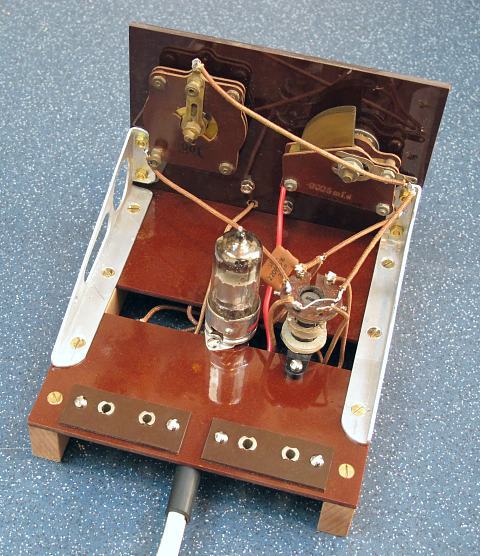
(back of an old consumer unit), and are each 1 3/4" x 11/16".   The fixing and socket holes are at 1 1/4" centres and 1/2" centres respectively.   This row of four holes is displaced 1/16" from the centreline of the strip as is my genuine example (to allow for printed legends).

The receptacles themselves are of 28swg sheet brass, rolled round a 1/8" drill.   These were each peened over at one end to form a flange, flattened at the other end to form a solder tag, and this tag drilled with two small (1.5mm diameter) holes.   They were knocked into very slightly undersize holes in the Paxolin strips, then secured with rings of copper wire (from house-wiring cable) soldered in position.

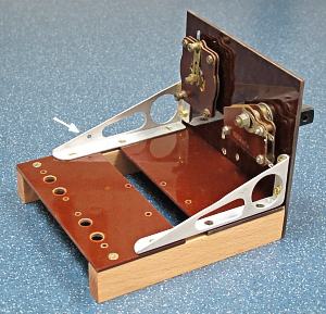
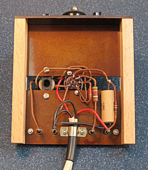
Each socket strip is fixed with two 6BA bolts and nuts (as I think was the case with my original 1957 set), rather than fixing the outer ends with wood screws through to the runners as the leaflet shows.   The 1/4" extra width to my chassis allowed room for the saddle and sleeve supporting the battery leads (see below).

Other components

The following components kept from the 1957 set are again used in my new rebuild:

* aluminium side brackets (not in published design);
* LT switch (not in published design);
* two variable capacitors;
* B7G valveholder;
* Teletron D/R coil.

The Teletron coil is now very scarce, and I am fortunate in having kept mine.   (If you want to build the Studio ‘E’ set but cannot get hold of this coil, you may like to consider making either the homebrew medium-wave-only coil that I tried out on my “conjectural” set, or the even bigger Davey long- and medium-wave coil.   Details for both of these can be found on the CONSTRUCTION RESOURCES page.   If you do use either of these large home-made coils in place of the Teletron, bear in mind that it will be necessary to offset the valveholder well towards the right-hand side of the chassis as seen from the front, and in the case of the dual-band coil, this will project somewhat above the front panel and also requires a wavechange switch.)

The control knobs and battery plug are also probably from the 1957 set.   I still have the original DAF96 valve, but I suspect this is a little low on emission, and I get better results with a (possibly newer) DAF91.

The three resistors and the grid capacitor (C3, 220pF) are “new old stock”, bought on ebay.   The only modern component is the bypass capacitor (C4, 0.1µF).   This came with a garish glossy yellow cover, so I took this off and substituted a "vintage-look" sleeve of manilla paper.

Top view.    

I made vintage-look sleeving by stripping 
the centre threads out of light-switch 
pull cord and painting the remaining 
braided sleeve with knotting varnish.
Wiring

For the "conjectural" set, I had made vintage-look sleeving by stripping the centre threads out of nylon light-switch pull cord and painting the remaining braided sleeve with knotting varnish.   I was able to re-use many pieces of this for the new rebuild.

The top view wiring differs a little from the leaflet due to the positions of the terminals on the variable capacitors.   Thus the ground line is one continuous wire from C2 (moving), to C1 (moving), to coil 2, to coil 4, to valveholder 1.

Yes, I know the tuning capacitor looks crooked – it has to be that way so that the flat on the shaft allows the control knob to sweep exactly from 9 o’clock to 3 o’clock!

The wiring to the LT switch is, of course, additional to that shown in the leaflet.

Bottom view.    

The large capacitor (C4) came with a garish 
glossy yellow cover, so I took this off and 
substituted a vintage-look sleeve of manilla paper.
In my original 1957 set, the battery connections were separate unsupported wires to the 4-pin battery plug, vulnerable to breaks.   As for the “conjectural” set, I have used two lengths of twinflex (red and black cores) passed through a rubber sleeve which is secured by a saddle held by the inner two fixing bolts for the wander sockets.   I also added a metal sheath to the plug.

I have also squared up the arrangement of the under-chassis resistors and capacitor, using the space to the right of the valveholder.   Thus, R2 does not cross and re-cross other wiring, and R3 is not snaked.   I routed most of the ground connections direct to the earth socket.

You may like to compare my new rebuild with Hugh Castellan’s Studio ‘E’ set, built very much as the leaflet specifies, and also with David Green’s “conjectural” set which, like my earlier rebuild, was put together before the Studio ‘E’ leaflet was rediscovered – see YOUR DAVEY SETS.

Performance and Listening

Powered either by my rechargeable battery pack or a mains-operated power supply (see below), my set operates well on about 14 metres of aerial in the loft.   Reaction works well over virtually the whole medium-wave band.   Spanish, Polish and Russian stations have been heard.   The new rebuild seems to perform about as well as the “conjectural” set did.

The medium-wave band is now something of a desert, as its use for a.m. broadcast declines.   The hallowed 208 metre (1440 kHz) spot on the dial once occupied by Radio Luxembourg is now taken by China Radio.   A mild dose of nostalgia can be had on Gold (music from the 60s, 70s and 80s) from about 38 local transmitters at various spots on the band.

My home-made battery pack,    
ready for use.    

I weighed the merits of building either a mains-
driven power supply, or a power pack using 
rechargeable batteries.
Rechargeable power pack

For the "conjectural" set, I had weighed the merits of building either a mains-driven power supply, or a power pack using rechargeable batteries.

I decided to build a pack using NiMH rechargeable batteries.   My unit has ten PP9 rechargeables in series (8.4 volts each), and four AA rechargeable in parallel.

Many builders or restorers of battery sets make up rechargeable battery packs using scans of the old battery types - for example see David Green’s “conjectural” set on YOUR DAVEY SETS page.   I decided to house my battery pack in a case made of beech and 3mm Tufnol.

I had made my own decision on how to wire the power plug and socket (see picture).   As it happened, when I checked on the Thompson Brown family site that carried many details of obsolete batteries, I found that I had got all four connections correct.   Unfortunately, as at November 2018, this very useful site seems no longer to be online, but see CONSTRUCTION RESOURCES.

The battery pack with    
the lid removed.    

. . . gold-plated steel twin conical springs 
(I just happened to have these!) . . .
The lid, secured with four brass "side hooks", carries the following:

* a home-made socket with contacts of phosphor bronze (fiddly to make!) to receive the original 4-pin battery plug;

* gold-plated steel twin conical springs for the series HT links (I just happened to have these!), carried on a paxolin plate.   Up to 84v is available in 8.4v steps by re-positioning the HT+ve connection – photo shows this positioned for 67.2 volts.   I could instead have simply poppered the PP9s together with their male and female connectors, but I had the springs to hand and thought that their use would make it easier to remove the batteries for recharging and make a more elegant package.

* parallel LT-ve connections - four nickel-plated steel conical springs soldered to a square brass plate.

The LT+ve connection in the base of the pack is a square brass plate (same size as that seen on the lid) with four upward-facing pips (centrepunched), from which a wire goes to the 4-pin socket via a spade connector.   Splitting this allows the lid to be removed entirely.

Two Tufnol bulkheads form a small compartment between the two battery banks.   This houses the tails of the 4-pin connector and the surplus wires leading to them, which are tidied with a short length of plastic sleeving.

The battery pack has been entirely reliable, with no evidence of crackling, and many hours of listening have been undertaken with it.   One disadvantage is that, after some months without use when other commitments intervened, I found that some of the batteries were fully discharged and were not recoverable.   As an alternative, I have recently (2021) built a mains-powered battery eliminator to a modern published design, providing both HT and LT.   Other mains-powered eliminators are available complete or as kits.

BACK TO TOP
CONTACT ME
For a link to the design I used for my mains-powered pack, details of a ready made HT/LT unit, details of home-made coils to use in place of the commercially-made one, and a list of useful suppliers, see the CONSTRUCTION RESOURCES page.

I would be delighted to hear about YOUR Studio E set!