AM broadcast decline:
|
|
The BBC and other broadcasters have been deserting the medium-wave band in favour of digital
technology over the past few years, and there is uncertainty about the future of the BBC's
long-wave transmitter. This trend, accelerated by online streaming services and smart
speakers, seems likely to continue, and is bad news for those who enjoy using simple radio
sets like many Davey designs, or commercially made radios from pre-FM or pre-digital days.
At present (2021) FM broadcasting does not seem to be under immediate threat.
There are several options for continued enjoyment of AM receivers. Not all options are
suitable for the simpler Davey sets. Please note that the
options involving direct connection of an external source to the set are potentially UNSAFE
for any receiver which does not have an isolated power supply (typically AC/DC type without
a mains transformer) unless special precautions are taken. If in any doubt, consult
a qualified person.
The options are:
1: If the set has a pickup input, most modern audio sources such as CD players or MP3 players
can be adapted to provide a suitable signal by attenuating and combining the stereo channels.
Commercial sets with pickup inputs usually have isolated power supplies, but they
should be checked by a qualified person if there is any doubt.
2: If there is room in the cabinet, a Bluetooth adaptor can be fitted internally, perhaps
powered from the set itself, but care is needed in order to provide a suitable supply for
the adaptor, and for a safe and reliable installation, whether the set has an isolated
power supply or not.
3: A very new development is a digital adaptor that can be fitted in place of the mixer
valve of a superhet receiver, deriving power from the radio itself. The device carries
out a search during the warm-up period, then spaces digital stations across the dial.
These devices are being produced in small quantities in Germany, but are expensive as they
have to be tailored to each radio model. They are nevertheless an interesting idea
that provides an entirely reversible upgrade. For more info, see:
https://www.vintage-radio.net/forum/showthread.php?t=175036
4: Another new development is an FM converter on a small PCB that connects to the tuning
capacitor of an AM radio. The device produces an audio output which is fed to the
radio's audio stages. Once again, special precautions must be taken if the set is
an AC/DC type. Also, precautions must be taken against electrostatic discharge
(wrist band, suitable footwear and clothing, etc) while installing. Because
nothing else can be connected to the tuning capacitor, it is necessary either to forfeit
AM coverage in the radio, or to install switching to select between AM and FM.
Further information at:
https://www.vintage-radio.net/forum/showthread.php?t=185018
5: Perhaps the simplest solution - if the radio does not have a pickup input - is a
"Pantry transmitter". This device accepts a signal from an audio source (e.g.
a phone tuned to internet radio or playing stored music, or a modern radio),
modulates the audio on to a carrier wave whose frequency is set to a quiet spot on
the receiving radio's dial, and radiates a very low-power signal (a few milliwatts
only) via a short aerial wire which is simply placed near the receiving radio.
It is suitable for most receivers, as it does not involve any direct electrical connection
between the two. For more info on one popular self-build pantry transmitter, see:
https://www.vintage-radio.net/forum/index.php
and search for "Mini-Mod" using the "Search this website" facility to view numerous threads on
this device. You should check whether such devices are legal or not in your country,
but they are unlikely to cause nuisance thanks to the very low power.
|
Battery:
|
|
As the old combined HT/LT types are no longer obtainable, many constructors make up replicas,
with rechargeable batteries inside cases carring colour scans of the old covers. This
thread in the UK Vintage Radio forum carries many battery case scans:
https://www.vintage-radio.net/forum/showthread.php?t=109240
- but Post 3 linking to the very useful Thompson Brown site no longer works.
|
Battery eliminator
for valve receivers:
|
|
As an alternative to a battery pack using rechargeable batteries, I recently (2021)
built a mains-powered unit to power my one-valvers. The design is by Paul
Stenning (owner of the UK Vintage Radio Repair and Restoration Forum), and very
comprehensive details can be downloaded at
http://www.vintage-radio.com/projects/battery-set-psu.html.
The design uses a readily available transformer with two 15-volt secondaries.
One of these supplies a voltage quadrupler circuit for HT, delivering 85 - 90 volts
at up to 15mA. The other secondary supplies an LM317T voltage regulator for LT,
adjustable by choice of component values in the control circuit. With the
values suggested, the 250mA maximum output is fixed at 1.35 volts, to prolong
the life of 1.4-volt filaments. The HT and LT sections are designed to be
entirely separate, to cater for radios that use biased filaments.
My unit is built into a small project box, 150 x 100 x 60mm, with ribs to accept PCBs
(or tagboards in my unit), with the outputs led to a four-way socket (no doubt
salvaged from an old HT/LT battery, and bought several years ago with an eye to this
purpose). Although, as mentioned above, the HT and LT sections are entirely
separate, with a simple one-valver the supply negatives are connected together
within the set and led to earth. The transformer insulation is more than
adequate to allow the unit to be used in this way.
A ready-made battery eliminator is available from 6V6 Electronics at
https://www.6v6.co.uk/psu.html
|
|
Battery plug, HT/LT, 4-pin:
|
|
I have never seen these on sale anywhere except at the National Vintage Communications
Fair (q.v.). Post 25 of this thread carries useful dimension information (diagram
7 is the common 4-pin connector):
https://www.vintage-radio.net/forum/showthread.php?t=71256&page=2
See also
My Rebuilt Studio ‘E’ Set
|
|
British Vintage Wireless Society:
|
|
The British Vintage Wireless Society
has 1700 members throughout the world who share practical, historical or technical
interests in vintage radio and television. A beautifully-produced Bulletin
is published four times a year, containing articles on all facets of the subject,
Society news, and details of events. These include swapmeets and auctions held
in various parts of the country, and the National Vintage Communications Fair (q.v.).
The Society produces DVDs containing archive films of technical and general
interest, and members can purchase a range of fixed capacitors suited to restoration work.
|
Capacitors, variable:
|
|
Many air-dielectric types are usually to be found on ebay, but the solid-dielectric types
are getting hard to find. Until recently, Mailine Group offered new "Dilecon" solid-dielectric
capacvitors, but their site has disappeared. Hopefully this signifies only a temporary problem.
|
|
Capacitors, fixed:
|
|
Members of the British Vintage Wireless Society (q.v.) can buy from a range of small-value and
electrolytic capacitors. Vintage types often appear on ebay.
|
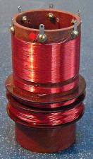
Coil, medium/long wave,
to Davey design
(Boy's Own Paper, Jan 1961):
|
|
This versatile coil has aerial, medium-wave, long-wave and reaction windings. Like most
homebrew coils, this is a bulky item at around 4 inches high and 2 3/4 inches diameter.
But this genuine Davey design is a worthy substitute for the commercially-made coils (Teletron D/R,
Repanco DRR2) which gradually went out of production in the 1960s and 1970s. If made
as well as the example pictured here, it will enhance any set! This one was kindly made
for me by Hugh Castellan, whose own version of the Davey triode one-valver (see
YOUR DAVEY SETS) uses the same coil design. I have since used
this splendid coil in a Davey one-valve design see THE BEGINNER'S 1-VALVER.
The design for this coil was first described in the January 1961 edition of Boy's
Own Paper, and subsequent editions described its use in transistor and one-valve sets.
The one-valver circuit diagram and components list are included in the download; the circuit
diagram has been corrected (April 2014) for two errors recently spotted.
By kind permission of Lutterworth Press, the PDF download below carries full details of this
coil, and is available for your personal non-commercial use. Please also read the
copyright notice on the WELCOME page. If you wish to
pass it on to a friend, please send a link to this web page. He will then have access
to the viewing and printing suggestions as below.
The download contains:
* the full January 1961 BOP article, including a crystal circuit using the coil;
* one-valver circuit diagram and components list from the June 1961 edition;
* notes on the design and its publishing history.
 PDF file: (You need Acrobat Reader installed on your PC.) File size is
3Mb, and a broadband connection is recommended.
PDF file: (You need Acrobat Reader installed on your PC.) File size is
3Mb, and a broadband connection is recommended.
Click the icon to download the PDF file. If Acrobat Reader opens within your
browser, use the "Back" button to return to this page when download is complete.
If Acrobat Reader opens in a separate window, close that window to return to this page.
Images and text are positioned so that when printed on one sheet of A4 paper,
the sheet can be folded to form an A5 leaflet. Some enhancement has been applied
to parts of the images to increase legibility. The BOP images are sized
at around 85% (linear) of true size.
|
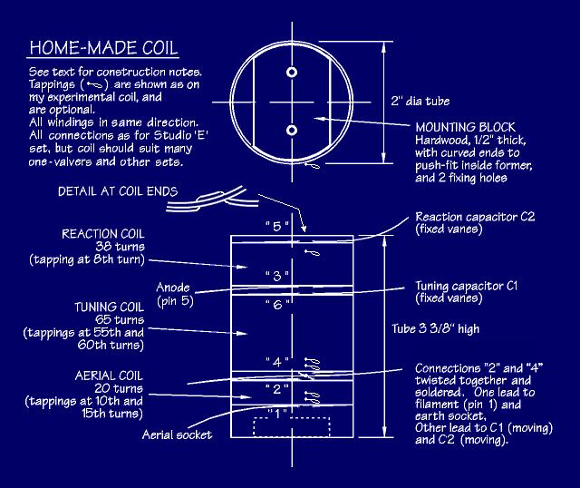
Coil, Teletron D/R,
home-made substitute:
|
|
When I came to rebuild my Studio ‘E’ one-valver, I was fortunate in having
kept many of the components that went into my original set. Of these, the Teletron
coil is the hardest to find these days, so here are details of the home-made coil which I
tried out in my "conjectural" set, built before the Studio ‘E’ leaflet came
to light. It is simpler and less bulky than the Davey-designed coil above, but in
common with the Teletron D/R coil for which it is intended as a direct substitute, it only
offers medium-wave reception.
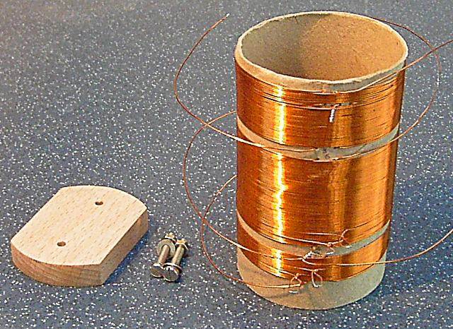
|
|
Experimental Teletron D/R substitute coil, after
adding extra turns to the reaction winding.
|
This coil was inspired by the one described for the first (February 1948) version of the
Beginner's One-valver, but took account, using other published data, of the wire I had
to hand. It was then altered as described below, in the light of trials on my set.
The coil former is a 2-inch diameter cardboard tube from kitchen roll, the same
diameter as a toilet-roll tube, but more to hold on to (the surplus length can
be cut off on completion). There are three windings (to replicate the
Teletron coil), all of 26swg enamelled copper wire. All windings are
close-wound, and all in the same direction – on my coil they form "right-hand
threads", spiralling clockwise and away from the viewer looking from above.
I included tappings as below for experiment, formed by twisting a small loop in
the wire at the completion of a turn, and then continuing winding. These
loops were scraped clean of enamel when the coil was finished.
During winding, the supply reel was placed on a screwdriver held vertically in
the vice so that it could turn freely, minimising the possibility of kinking the
wire. At the beginning of each winding, a pair of small holes about 1/4”
apart was punched through the tube with a needle, about 9” of wire was threaded
through (in one hole, out the other) for connection, then turns wound on as below.
When each winding was complete, the wire was cut to leave another 9” for
connection, two more holes were punched, and the wire threaded in and out.
The gaps between windings are about 1/4”. The windings are:
Reaction (top), 30 turns initially. After trials I added a further
8 turns at the top, leaving the original start as a tapping at the 8th turn
of a 38-turn winding.
Tuning (centre), 65 turns, with tappings at the 55th and 60th turns;
Aerial (bottom), 20 turns, with tappings at the 10th and 15th turns.
The drawing sums up these details.
The numbers in quotes correspond to the tag numbering on the Teletron coil.
The destination of each connection is given for the Studio ‘E’
one-valver. Note that for this set, connections "2" and "4" are stripped of
enamel for a short distance (say 3/8”) where they leave the former, and are then
twisted together and soldered. This forms the grounded connection between
the aerial and tuning windings, with two long leads from the junction.
To mount the coil to the chassis, I made a hardwood block, about 1 3/8” wide
and 1/2” thick, with curved ends for a push-fit inside the former, and drilled
fixing holes. With this block bolted to the chassis, the coil slips over
it. Take care that the block does not foul the end of the aerial winding
where the wire is inside the former.
After trials, I found that the full complement of turns on both the aerial
and tuning windings worked best, so the tappings on these were redundant.
With the reaction winding as first made, I found that reaction was rather less
lively than with the Teletron coil, so I wound on the 8 extra turns as stated.
Using all 38 turns, performance seemed to be about the same as with the
Teletron coil, although I could not of course make instantaneous comparisons.
The tapping so formed was therefore also redundant.
If you are using the same gauge of wire and don’t want to experiment, you can
just make the coil with the full number of turns (38, 65, 20), without the
tappings. If you use a different gauge of wire, you may need to experiment
with the number of turns for each winding. You may also want to consider
painting the completed coil with clear polyurethane varnish, to strengthen the former and
fix the windings in place.
My correspondent David Green has copied this coil - without the tappings - on his
own "conjectural" Studio ‘E’ set (commenced before the leaflet
came to light), and has achieved good results - see YOUR DAVEY SETS.
I have not tried this coil on my new Studio ‘E’ rebuild
(see My Studio ‘E’
Rebuild), but I have no reason to doubt that it would perform equally well in this set.
Note: If you follow the Studio ‘E’ leaflet's layout, the coil will
go on the left of the set as seen from the front. The leaflet shows the valve
mounted centrally in the slot, but in order to place this large home-made coil in the
correct position, it would be necessary to shift the valve well to the right as seen
from the front of the set.
|
|
Components, vintage:
|
|
Geoff Davies Radio, (tel: 01788 574774, email: geoffdavies337 (at) gmail dot com) sells a good selection
of valves, vintage components, sundries and radio books. He also often has interesting
items of equipment that could serve as projects in their own right. No web site, but
you can subscribe to his monthly list.
|
|
Control Knobs:
|
|
The annual National Vintage Communications Fair (q.v.) is a useful source, as also is ebay.
|
|
ebay:
|
|
https://www.ebay.co.uk/ What would
we do without ebay? You can find just about anything on ebay if you
keep looking, and I have had extraordinarily good service from many sellers who
understand what they are selling. Some sellers do not. In the case of
components, this often means that the seller is unable to say whether the item is in
working order. For books, there is often no information about which
edition of a work is on sale, or (worse) incorrect information. Caveat emptor!
|
Headphones:
|
|
These always seem to be on offer on ebay, but sellers sometimes don't understand what
they are selling and have not tested them. It can take several attempts to buy a
satisfactory pair, and knowledgeable sellers such as those at the National Vintage
Communications Fair (q.v.) may be a safer bet. Test a pair by putting them on,
and connecting a 1.5v cell across the leads; a healthy crackle should result.
|
|
Maplin:
|
|
Went into administration on 28 February 2018. Web site now appears to be inoperative.
|
National Vintage
Communications Fair:
|
|
See Retrotech UK.
|
|
Pantry transmitter:
|
|
See AM broadcast decline.
|
|
Resistors:
|
|
Several ebay suppliers have stocks of vintage "new old stock" resistors.
|
|
Retrotech UK:
|
|
https://www.retrotechuk.com/ Held
every May at the Warwickshire Exhibition Centre, and open to all, this one-day event, formerly
known as the National Vintage Communications Fair, is staged by the British Vintage Wireless
Society (q.v.) It must be one of the best opportunities to buy vintage equipment,
parts and reference material.
|
|
Sleeving:
|
|
The old yellow "Systoflex" sleeving seems to be available no longer. I made vintage-look
sleeving by stripping out the centre strands from white nylon pull-cord, then painting it with
knotting varnish. Geoff Davies Radio (see Components, vintage) stocks 2mm bore black
vintage-look sleeving, useful when you want to cover a joint mid-way along a wire run, but
rather big for general use.
|
|
Transformers:
|
|
https://www.transformers.uk.com/
The Majestic Transformer Co can manufacture custom mains and output transformers for
valve-based sets.
|
|
Transistor data:
|
|
https://alltransistors.com/ Datasheets
for all types of transistor.
|
|
Transistors:
|
|
https://www.langrex.co.uk/ Langrex have a
wide range of new-old-stock semiconductor devices. They sell on ebay as "yitry".
|
|
Tufnol sheet:
|
|
https://www.directplastics.co.uk stock
Tufnol sheet in a variety of grades and thicknesses. The modern equivalent of
Paxolin.
|
UK Vintage Radio Repair and
Restoration Forum:
|
|
https://www.vintage-radio.net/forum/index.php
Invaluable source of information and advice on all aspects of vintage radio.
Threads detailing useful suppliers, components and equipment wanted or on offer, basic
and not-so-basic technical issues. Some very funny and entertaining threads too!
|
|
Valve data:
|
|
The National Valve Museum at
http://www.r-type.org/index.htm
is a "virtual" collection of valve data, photos and articles covering theory and practice.
Another good source of valve info is
https://www.radiomuseum.org/dsp_searchtubes.cfm.
|
|
Valves:
|
|
Most types still seem to be available as "new old stock" via ebay. Langrex
(see Transistors) sell on ebay as "yitry".
|
|
Valveholders:
|
|
From ebay sellers, Geoff Davies Radio (see Components, vintage), or at Retrotech UK (q.v.).
|
Wander plugs and
socket strips:
|
|
The traditional 1/8" wander plugs and paired sockets are hard to find now - the National
Vintage Communications fair (q.v.) is perhaps the best chance. See
My Rebuilt Studio ‘E’ Set for how I
fabricated my own paired sockets from 1/16" Tufnol and sheet brass. Several ebay
suppliers stock the modern 3mm or 4mm "banana" plugs and single sockets.
|
|
Wire, connecting:
|
|
Tinned copper wire can be salvaged from old stranded house-wiring cable. Other
alternatives are 15 amp fuse wire (expensive, though), or insulated equipment wire.
|
|
Wood screws:
|
|
Brass screws are good to use where appearance is important, but it is always a good idea to
form the thread in the wood with an equivalent steel screw first, so as to avoid the risk of
shearing-off the brass screw.
|