These rebuilds amount to no less
than a rescue from oblivion . . . YOUR DAVEY SETS
This page features sets built by contributors, according to or substantially inspired by any of Gilbert Davey's designs.   The first five are by Hugh Castellan, an experienced constructor, and include two "lost" designs that he has reconstructed from a combination of memory, experience, research, and some help from Gilbert Davey himself.   Downloads for these two designs are now available on this page - see below.   Other sets include several one-valvers, including one built by a newbie who was thrilled at his success, a splendid Davey shortwave two-valver, several sets using transistors or silicon chips, and a memory of a set for which only some paperwork remains.   I would be pleased to receive details of any Davey sets for consideration for this page, and especially for any of the early Boy's Own Paper designs which were not re-published later.


Welcome and introduction,
contact details, disclaimer,
rights notice, BVWS link,
site map.
The man who introduced radio
construction to several generations
of boys, many of whom became radio
or communications professionals.
The history of the famous
one-valve circuit, 1948-78.
The Studio 'E' 1-valver and
the Focus Transistor radio:
downloads for these famous
designs, and lots more!
This portable receiver clearly became 
very popular, as it was published seven 
times from 1962 to 1981.
A growing resource for those who
built Davey designs years ago, or who
simply wish to know more about them.
(This page)
Davey sets built by contributors -
including designs that could have been
lost but for some prolonged detective work.
Two home-made coils to use in place of the all-too-scarce
commercial types, suppliers for other components, and
other sources of useful information.
Latest news, links to other sites of interest,
and news archive.
Hover your mouse over the
navigation buttons above for
brief page contents.
Pages marked  >  give access to
one or more subsidiary pages -
see also Site Map at bottom
of WELCOME page.
Please note:
If you decide to construct any of the sets described or referred to on this page, it is your own responsibility to ensure that you work safely and that equipment (especially mains-operated sets or power supplies for battery sets) is soundly built and adequately housed.   Whilst considered safe by the standards of their day, some designs may not be considered safe by modern standards.   If you are in any doubt about your understanding of the information given or referred to on this page or about your ability to work safely, you should seek the help of a qualified person.


Hugh Castellan's sets

Hugh Castellan recalls building radio sets from the Boy's Own Paper during the 1950s while at school; these sets were lost over the years.   From the 1980s onwards he started again and, with some initial help from Gilbert Davey himself some years ago, and much detective work of his own, he has built five Davey designs altogether.

The original sources for the first two sets are long out of print, but can be found occasionally on internet auctions and bookseller sites, or by recourse to the British Library.   For the second two sets - the Holiday Radio and the Simple Three-valve set - the full original details are now almost certainly irretrievable.   Because of post-war paper shortages, Davey's designs were often published with incomplete details; the BOP only sent the remaining information out as duplicated sheets to intending builders.   It is extremely unlikely that any of these sheets have survived.   These rebuilds thus amount to no less than a rescue from oblivion.   Downloads compiled from Hugh's design details, and including the original BOP articles, are now available on this page - see below.

1: A modern Davey one-valver with a flavour of the past
First, his Davey one-valver.   Whilst the circuit is based on the original triode design as published (with reasonably full details) in the Boy's Own Paper in February 1948, it uses Davey's later long- and medium-wave coil as published in the January 1961 BOP (see CONSTRUCTION RESOURCES page for a download of the January 1961 article).   Also, Hugh has departed from Gilbert Davey's 1948 layout; instead his radio has a distinctive retro feel of its own.   He writes:

Hugh Castellan's one-valver, top view. Hugh Castellan's one-valver, bottom view.
    Hugh Castellan's one-valver, built on a
    Perspex panel; top view.


    Reproduced by kind permission.

    Hugh Castellan's one-valver, bottom view,
    showing the beautifully made coil.


    Reproduced by kind permission.

My one-valve radio is designed to go into a wooden case of suitable size.   The layout is based on a genuine Burndept crystal set which I own - the valve replaces the Cat's Whisker.   It was designed to look as old fashioned as possible, hence the black Perspex base to simulate Vulcanite.

The old balloon valve is a triode which seems to be very close to the HL2 in characteristics; it is numbered 542 on the base, but otherwise has no ID.   The valveholder is just four turned parts screwed into the panel.

The two terminals at top left are alternative aerial terminals, and the one at top right is the earth terminal.   The bottom terminals are for the headphones (S G Brown high impedance).

The coil is wound on a piece of Tufnol SRBP tube.   The small switch is the wavechange switch.   The variable condensers are genuine Jackson originals; otherwise the components are modern.

For the HT supply, I use seven PP9 equivalent batteries (i.e 63v).   I use a 2v 8AH sealed-for-life accumulator for the LT, which I charge with a modern electronic charger made in Germany.


The coil windings are long-wave, reaction (these two pile-wound within retaining rings), aerial, and medium-wave.   This coil, with lacquered windings, appears to have been beautifully made, as indeed does the whole set.


2: The Cycle Radio,
Boy's Own Paper, March 1952,
reprinted in Fun with Radio,
1st edition, 1957,
2nd edition, 1959,
and 3rd edition, 1961.
Hugh Castellan's Cycle Radio    
Front, rear and bottom views.    

Reproduced by kind permission.    

Hugh Castellan's Cycle Radio,
front view.
Hugh Castellan's Cycle Radio,
rear view.
Hugh Castellan's Cycle Radio,
bottom view.
The original BOP notes were only a written script with no diagrams, but fortunately Gilbert Davey included the Cycle Radio in the first three editions of Fun With Radio.   The simple design has detector and two LF stages, and is intended to receive local stations with a short aerial.

The design nearly didn't make it into the second and third editions, as Davey considered it out-of-date and the valves were unobtainable.   But, as his Author's Note in the second edition tells us, on the very day he had decided to exclude it, he received a letter from a New Zealand reader thanking him for the pleasure it had given him.   It brought home to him the realisation that in many parts of the world the set's relatively poor selectivity was no problem, and that its dependence upon batteries was a positive advantage where mains supplies were unavailable.   As a compromise, he gave alternative 1.4-volt valve types to use, with substitute connections.

Hugh's set was made to the original design (he had not made this set as a boy).   He writes:

The valve line up is HL2K, PM2HL and PM22A.   The coil is homemade, or you could originally use the specified alternative of the Wearite PHF7 coil.   Both coils are for medium waves only.   The front panel has the usual tuning and reaction controls.

The aerial I used is an extending radio control aerial, but I imagine that builders would have used some surplus "38 set" aerial which was commonly available then.   The socket on the left is the earth connection - the set works without an earth but is much better with one.   Gilbert told his clients to use the set only when stationary, so a length of brass curtain or stair rod with a wire would have made a good earth.

The two sockets on the right are for the separate loudspeaker which was mounted on the handlebars.   The set itself was mounted on the crossbar, and the batteries were in your saddle bag.


I wonder how many of these sets were actually mounted to bicycles - a box of the suggested size on the crossbar would surely have been a nuisance if mounted above it and a knee hazard if hung below.   I asked Hugh if he had tried mounting his set on a bicycle.   His reply:

No, I haven't tried it on a bicycle as I don't have one - far too old at 72 for bikes I'm afraid!

If you built one of these sets and fitted it to a bike way back in the 1950s, please tell me about it.


3: The Holiday Radio,
Boy's Own Paper, July 1950 -
reconstruction of a
"lost" Davey design.
Download with
full details available
on this page
Hugh Castellan's Holiday Radio    
Front, rear and bottom views.    

Reproduced by kind permission.    

Hugh Castellan's Holiday Radio, front view.
Hugh Castellan's Holiday Radio, rear view.
Hugh Castellan's Holiday Radio, bottom view.
Hugh Castellan's Holiday Radio rebuild was finally completed quite recently, and is the result of detective work and brain-cudgelling over many years.   This Davey design was published in the July 1950 Boy's Own Paper, but readers had to send for a separate leaflet containing the circuit diagram and components list.   The intention was that this small lightweight radio without internal battery storage space should be taken on holiday, and powered by batteries bought while there.   A 30-foot length of wire thrown over a tree branch served as an aerial.

Whilst a boy at school, Hugh sent for the plans and built the set.   The specified valve line-up was W21 7-pin (RF), HL2K (detector) and PM22A (output).   Hugh remembers:

In my original set, I used a 7-pin VP2 instead of the W21 - this was the Mullard equivalent which a radio shop man in Burton-on-Trent said would do the job.   I was only 12 years old and not very knowledgeable at the time, so had to hope he was right.   I used a standard HL2 instead of an HL2K.

This set - and the plans - were lost over the years.   And there it rested until the 1980s when he started again.

I wanted to build a new Holiday Radio, so my wife wrote to Practical Wireless on my behalf asking if anybody still had the plans.   I did get a phone call from Gilbert Davey himself but he was unable to help me with the Holiday Radio.   He sent me one of his books and some data on that big 2" diameter coil.   [See the 1-valver above.]

I went to the British Library and obtained prints of the Holiday Radio, the Simple Three Valve Radio, and the Cycle Radio, plus some info on the One-Valve Radio and the Crystal Set.   But of course there were no circuit diagrams with some of the notes as you know.

I drew out circuit diagrams and sent those off to Mr Davey who kindly marked them up for me as far as he could go.   I partly built the Holiday Radio, but did not have all the circuit details.   And there things stood until recent times.

Certain components stuck in memory - 10k anode resistor for the VP2 and 100k anode resistor for the HL2 were remembered purely because of the colours - and the 8μF bypass capacitor in the cathode circuit of the PM22A output valve.

The Holiday Radio rebuild is as near to the original as possible with what I had to make it with.   The line-up is W21 4-pin, HL2K and PM22A.   Gilbert Davey originally specified a 7-pin W21, but I have never found one yet although they were made according to some data I found recently.   The W21 was always upside down because it only fits that way given the case size.   The coils are homemade to the original specification written in BOP.   However I used Litz wire for the tuning windings and solid wire for the reaction winding.   I placed the battery socket slightly differently as it was not very secure as designed.   The case should be covered with Rexine, but I have not got round to using something like this.   I rather like seeing the inner works.


Later, Hugh found a 7-pin W21, so his Holiday Radio now has the authentic line-up.   The output transformer seen in the photo has also since been replaced with a special transformer made to suit the PM22A output valve.

By kind permission of Lutterworth Press and Hugh Castellan, the PDF download below carries extensive details of the reconstructed Holiday Radio, and is available for your personal non-commercial use.   Please also read the copyright notice on the WELCOME page.   If you wish to pass it on to a friend, please send a link to this web page.   He will then have access to the viewing and printing suggestions as below.

The download contains:

* the full July 1950 BOP article;
* circuit diagram, components list, construction notes;
* annotated high-resolution photos of the set.
Minor corrections have been made to the leaflet (1.1.2014).   A drawing for constructing the cabinet is in preparation.   A new PDF will be uploaded when this is ready.


Holiday Radio, A4 PDF file PDF file:   (You need Acrobat Reader installed on your PC.)   File size is 1.6Mb, and a broadband connection is recommended.

Click the icon to download the PDF file.   If Acrobat Reader opens within your browser, use the "Back" button to return to this page when download is complete.   If Acrobat Reader opens in a separate window, close that window to return to this page.

Images and text are positioned so that when printed on two sheets of A4 paper, the sheets can be folded to form an 8-page A5 leaflet.   Print odd pages first.   Turn the two sheets over, and print even pages.


4: The Simple Three-valve Radio
Boy's Own Paper,
November 1949 -
another "lost" Davey design.
Download with
full details available
on this page
Hugh Castellan's    
Simple Three-valve Radio    
Front, rear and bottom views.    

Reproduced by kind permission.    

Hugh Castellan's Simple Three-valve Radio,
front view.
Hugh Castellan's Simple Three-valve Radio,
rear view.
Hugh Castellan's Simple Three-valve Radio,
bottom view.
The November 1949 edition of BOP carried fairly full instructions for the Simple Three-valve Radio, including a circuit diagram and practical layouts.   Tantalisingly though, values were not shown for all components, and would-be builders had to send for the full list.   It was an "up-to-date" design with RF, detector and pentode output stages, simple enough for the relative beginner, but sophisticated enough to attract more experienced constructors.

The chassis floor serves as screening between the two coils, which are mounted at right-angles as a further safeguard against interaction.   (If a wooden chassis were used, foil covering was advised.)   Space is reserved in front of the output valve for the loudspeaker when built into a cabinet.   Original valve line-up was specified as W21, HL2, PM22A.   Hugh Castellan writes:

Here are three photos of the Simple Three Valve Radio, which was the second radio I built originally as a boy.   My modern one differs in the homemade valveholders and the output transformer mounted under the chassis which I think is safer than having 90 volts floating about outside the set.

The circuit is "pure Gilbert" from the printed article, and Davey himself checked it for Hugh when they were in touch during the 1980s.

With reference to output transformers, as far I can see Gilbert never specified an output transformer precisely.   I looked up the data for the PM22A on the internet. Both 15kΩ and 19kΩ were given in various data sheets.   My transformer gives 15kΩ max. I think 19KΩ is the preferred value.

Hugh has since fitted a new output transformer made specially for him to suit the PM22A.

The coils used on the Simple Radio were the Wearite 'P' coils type PA2 and PHF2 as per the original.   The 2-gang 500pF condenser is a genuine Jackson I bought in the 1980s when they were still in business.   I have long hoped to obtain the long-wave equivalent of PA1 and PHF1 but no luck so far.

By kind permission of Lutterworth Press and Hugh Castellan, the PDF download below carries full details of the Simple Three-valve Radio, and is available for your personal non-commercial use.   Please also read the copyright notice on the WELCOME page.   If you wish to pass it on to a friend, please send a link to this web page.   He will then have access to the viewing and printing suggestions as below.

The download contains:

* the full November 1949 BOP article;
* circuit diagram, components list, construction notes;
* annotated high-resolution photos of the set.
Minor corrections have been made to the leaflet (1.1.2014).


Simple Three-valve Radio, A4 PDF file PDF file:   (You need Acrobat Reader installed on your PC.)   File size is 4Mb, and a broadband connection is recommended.

Click the icon to download the PDF file.   If Acrobat Reader opens within your browser, use the "Back" button to return to this page when download is complete.   If Acrobat Reader opens in a separate window, close that window to return to this page.

Images and text are positioned so that when printed on two sheets of A4 paper, the sheets can be folded to form an 8-page A5 leaflet.   Print odd pages first.   Turn the two sheets over, and print even pages.

I am deeply grateful to Hugh Castellan for making available the information, based on his extended work, that has made possible these two downloads.   These two designs, so nearly lost, can now be enjoyed once more.


5: A "pukka" Studio ‘E’
One-valver,
BBC Television,
September - November 1957
Hugh Castellan's    
Studio ‘E’ one-valver.    
Front, rear and bottom views.    

Reproduced by kind permission.    

Hugh Castellan's Studio E one-valver,
front view.
Hugh Castellan's Studio E one-valver,
rear view.
Hugh Castellan's Studio E one-valver,
bottom view.
Hugh Castellan's latest build is a Studio ‘E’ one-valver as near to the design in the leaflet as he could get it.   With its plywood panels and no on-off switch, Hugh's set must look very like many others built during the TV series in 1957.   So this is very much a "pukka" version of Davey's design.

In November 2011, I happened to spot a Teletron D/R coil on the ebay auction site.   Knowing that Hugh wanted to build a Studio ‘E’ set, I gave him the tip-off.   He was lucky enough to win this rare item!   Hugh writes:

Please find enclosed some photos of my version of the Studio ‘E’ Gilbert Davey radio.   It works very well with Radio 5 Live, but it might need an increase in reaction capacitor to 300pF.

Both variable capacitors are modern ones made by the successors to Jacksons.   The wander plug sockets are home-made to look like the original as far as possible.   I use an outdoor aerial and an earth in the ground outside.   Headphones are my S G Brown high impedance ones - 4000Ω as far as I know.

I am using a DAF91 valve, and the HT is 63 volts.   However the resistor in series with the phones is 4.7kΩ, as 5kΩ is not a preferred value any more.


Hugh has used turned parts for the wander sockets - he found them impossible to buy as I did.   He has used the two inboard wander socket fixings, as I did, to secure a clamp for the battery lead.

Hugh's experience with the set's reaction accords with my own - my "conjectural" set was a little deficient on reaction at the LF end of medium wave, and so is my new rebuild.

By the way, I have turned the bottom-view photo upside-down, so that you can compare it more easily with the leaflet's layout - see The Studio ‘E’ Leaflet (open another tab in your browser and switch between tabs, or open a second browser session and see both at the same time).   You'll see that Hugh has "squared-up" the wiring a little, but it still follows the leaflet's layout closely.

My thanks to Hugh for sending me these pictures and notes.   I have now caught up with him, and have rebuilt my Studio ‘E’ largely in accordance with the leaflet, but I have incorporated once again the changes my father built into the original.   Compare our two sets - see My Rebuilt Studio ‘E’ Set


6: David Green's "conjectural"
Studio ‘E’ one-valver
In February 2011, David Green was looking for a simple beginner's project to introduce him to valve technology, and stumbled upon my site.   This was before the Studio ‘E’ leaflet had come to light, and the site then carried details of my "conjectural" Studio ‘E’ set (now replaced by details of my re-build according mostly with the leaflet).   With just a very few tips from me along the way, David has surmounted every obstacle that Murphy's Law could put in his path, including duff headphones (he re-wound faulty coils!), doubts about component choices, and dry joints.   At the end of September 2011, I received this message from David:

David Green's Studio ‘E’ set,    
built to my "conjectural" design.    

Reproduced by kind permission.    

David Green's 'conjectural'
Studio 'E' radio, front view.
David Green's 'conjectural'
Studio 'E' radio, rear view.
Just to let you know that I got around to setting up the aerial, earth etc.   I re-checked the headphones and to my surprise found one ear-piece seemed to be fully functioning so shorted out the other, plugged everything in and waited - nothing!   I thought maybe the valve was duff or I was wrong about the headphones, so today I went through checking everything.   Tried again and lo and behold there was the voice of Ed Balls speaking at the Labour Party conference!   Magic!   (The radio that is, not Ed Balls.)   I needed to re-solder a couple of joints but other than that it works fine.   I have to keep switching it on and twiddling the dials.   It's fantastic - I am absolutely thrilled.   Picture attached.   I would like to say very many thanks for your time giving advice and guidance - it is very much appreciated.   I would have made a lot of mistakes otherwise.
Best wishes, David.


Congratulations to David on his first one-valver!   It really is a lovely looking build, and I'm glad his patience through the various setbacks paid off.   Don't know about Ed Balls, but Gilbert Davey's magic still works for radio beginners of all ages!   As can be seen, David has made a coil as specified on the CONSTRUCTION RESOURCES page, and has made up a repilca HT/LT battery pack.   He has even copied the aluminium brackets that feature in my own Studio ‘E’ set!


7: Dan Bedford's
Shortwave Two-valver,
Fun with Short Waves
1st edition, 1960,
Chapter 4
Dan Bedford's Shortwave 2-valver.    
Front, rear and bottom views.    
Note the manufacturer's badge!    

Reproduced by kind permission.    

Dan Bedford's shortwave 2-valver,
front view.
Dan Bedford's shortwave 2-valver,
rear view.
Dan Bedford's shortwave 2-valver,
bottom view.
Dan Bedford, from Queensland, Australia, told me he intended to build a Davey one-valver.   Well, he's gone one better - he's built a two-valver instead!  It is based on Chapter 4 of Fun with Short Waves, 1st edition, 1960.   Dan writes:

It was this book, more than anything else, that set me off on a path of no return in radio and electronics.   It took me from the world of crystal sets into the wonderful world of valve radios.

For this set, Gilbert Davey specified his simple split-floor chassis as he used for the Studio ‘E’ set (see above) and for a shortwave one-valver in the first edition of Fun with Radio.   For shortwave work, the wooden chassis is covered in aluminium foil.   But Dan had trouble making the plywood panels:

This should have been very straightforward, but I found that the quality of the plywood left a lot to be desired and I had difficulty cutting and drilling it without splintering.   I had to score both sides of the ply with a Stanley knife before cutting, and clean holes could only be made by drilling tiny pilot holes and then carefully enlarging them from both sides.

It was my intention to be as faithful as possible to the original 1960 design.   To this end I used suitable British components, including Teletron valve sockets, Jackson and Ormond solid dielectric capacitors, and Bulgin switches, phone jacks and terminals.   I didn't have the Osmor coils that Davey specified, but I do have a collection of Denco coils of a slightly later vintage.   They had to suffice.

The detector is a 1T4, and the audio amplifier is a 3V4 wired for 1.4 Volts on the paralleled filament.
  [We show the parallel arrangement for the filament of this valve on the circuit diagram below.   Beware!   Pin connections for 1.4v valves vary between types, so check carefully before applying power to them.]

For wiring up, I needed to restrain myself!   My natural tendency is to use the correct wiring colour codes and appropriate passive components from the sixties.   I doubt that Davey would have been that pedantic.

The pictures show:
Top: the simple front panel, with neat legends, and complete with manufacturer's badge;
Centre: rear view, showing the foil-covered chassis and major components;
Bottom: underside view.   The coil socket is on the left; the output valve is on the right.

The Shortwave 2-valver:    
In red: Dan Bedford's changes and    
corrections to the published design.    

The shortwave 2-valver,
circuit diagram.


By using plug-in Denco coils, Dan eliminated the coil switch that featured in Davey's design.   The "front end" is thus very simple (see A above).   The pictures show the set fitted with a green Denco DP Range 2 coil.   Dan continues:

My first trials were not encouraging.   RF was bleeding through to the audio stage and causing distortion.   Improved decoupling was in order.   A 1000pF capacitor to ground from the detector anode load resistor (B) cured this problem.   I also decoupled the screen dropping resistor from the output stage (C).

Yet another problem!   Perhaps my Denco coil had a much higher 'Q' than the 1950s-60s coils that Davey used.   The regeneration was way too fierce.   The answer was to reduce the high screen voltage by increasing the value of the screen dropping resistor R5 (D) to 470kΩ.   Davey may have discovered the same, because he used a higher value for the corresponding component in the three-valve set later in the book.

Regeneration was still way too active, but a 4.7kΩ damping resistor (E) across the feedback winding tamed it.

Davey designed his set to use back bias on the HT+ supply to provide a source of negative grid bias for the output valve.
  [The circuit diagram in Chapter 4 is incorrect, but there is a footnote giving the correction.   We show the corrected arrangement here (F).]

Dan Bedford's Shortwave 2-valver:    
HT and LT batteries.    

Reproduced by kind permission.    

Dan Bedford's shortwave 2-valver,
HT battery.
Dan Bedford's shortwave 2-valver,
LT battery.
Dan needed high- and low-tension batteries for his set.   While in the UK, he took a trip down London's Edgware Road.   It was a wasted journey:

Of all the wonderful radio shops that were once there, I could only find Henry’s Radio (now Henrys Electronics).   The young man behind the counter had no idea what a high-tension battery was.   I would have to make one!

Having encased modern batteries in period packaging, Dan decided that they looked too new - he wanted batteries from the 1960s!   So they have been carefully distressed.

Dan says that the set's performance is limited at present as there is no bandspread provision, and no slow-motion gear on the tuning capacitor, which itself has a worn shaft.   (I also wonder if Dan has overdamped that reaction coil.)

However, he has gained much pleasure in building the set, and in December 2013, it was entered in the Two Valve Device Competition held by the Historical Wireless Society of South East Queensland, his local club.   Dan was awarded joint First Prize with the only other entrant!

My thanks to Dan for sending me his pictures and text, and for allowing me to reproduce them here.


8: Peter Munro's
Beginner's One-valver,
Fun with Electronics
2nd edition, 1972,
Chapter 2
Peter Munro's    
Beginner's One-valver.    
Front, rear and bottom views.    

Reproduced by kind permission.    

Peter Munro's one-valver,
front view.
Peter Munro's one-valver,
rear view.
Peter Munro's one-valver,
bottom view.
Peter Munro, from near Melbourne, Australia, has sent me pictures of his very workmanlike Davey one-valver.   Peter wrote:

In 1979, I wanted to build a one-valve radio, but I was advised to build a one-transistor radio.   About ten years ago I came across Fun With Electronics at a book sale, and built the one-valve radio a few years ago.   I recently pulled it out again to replace the regeneration capacitor I had stolen.   I don’t know why I used 90 volts HT.

Peter's one-valver is based on the version published in Fun with Electronics, 2nd edition, 1972.   Davey suggested a simple chassis on two runners, and specified either the Repanco DRR2 coil or a home-made one.   Peter has elected to use the home-made coil, which has aerial, grid (medium wave) and reaction windings.   I like the nice chunky brass terminals!

Peter powered the set initially using ten PP3s in a plywood box for HT, and a single 'C' cell for LT.   He was a bit disappointed with the set's performance, and thought at first that it may have been because he was using a transformer to drive low-impedance headphones.   Trials with a high impedance earphone were no better, with not many stations to be found on medium wave, but Peter intended to try some high-impedance headphones.

These one-valvers usually do very well with a reasonable length of aerial, and Peter's 90-volt supply should have allowed the set to be brought easily to the sensitive point of just failing to oscillate.   I wondered whether the position in Australia was the same as in the UK, with broadcasters deserting the medium wave band.   Following the May 2018 site update, my correspondent Graeme Zimmer (also in Australia) advised that there is still plenty to listen to on medium wave there.

I told Peter about this, and he has now tried his high-impedance headphones.   Results were much better, even with HT reduced to 45 volts, with about five stations coming in.   He does, however, have trouble with breakthrough from a Chinese language station 2 kilometers from his home, radiating at 5 kilowatts.

Peter has plans for other homebrew projects, and I look forward to hearing about these soon.


9: John Pugh's
Studio ‘E’ One-valver
John Pugh's    
Studio ‘E’ One-valver.    
Front, rear and bottom views.    

Reproduced by kind permission.    

John Pugh's one-valver,
front view.
John Pugh's one-valver,
rear view.
John Pugh's one-valver,
bottom view.
Yet another Studio ‘E’ set - to my knowledge this brings the total to four built since the rediscovery of the BBC leaflet.   John Pugh has sent me these pictures of his nicely made set.   He writes:

This is my attempt at recreating a long past memory.   Unfortunately, the coil is a Repanco DRR2 - I still cannot find the Teletron!   Other parts came from my junk box - sorry, I mean items in stock.   The Jackson caps are original, as is the valve, a DAF96.

The set is powered by an AA cell for LT, and a mains “Battery Eliminator” for HT of 64 volts.   It works fine, although there is a distinct lack of MW stations now.   Like your comment on your own set, reaction control is a little deficient at the LF end.   Please keep up your good work on your website.


Thanks to John for sending these pictures.   He may not have found the Teletron coil (keep looking!), but he has found some genuine wander sockets – very hard to find these days.   I wouldn’t mind betting that quite a few Studio ‘E’ sets were built with the Repanco coil and a wavechange switch – other coils were available in 1957, including the Repanco.   This coil has no aerial winding, but does have a long-wave winding.   John has shorted out the long-wave winding (blue to black) with a view to an experiment later.   Intriguing - I look forward to hearing about this.
 

10: Austin Hellier's
Simple Transistor Receiver,
Fun with Transistors
1st edition, 1964,
Chapter 3
Austin Hellier's    
Simple Transistor Receiver    

Reproduced by kind permission.    

Austin Hellier's Simple Transistor Receiver.
Austin Hellier, from Queensland, Australia, sent this picture of a radio set that fulfilled a childhood dream, held since as an eight-year-old he borrowed Davey's Fun with Transistors, 1st edition, 1964.   It is the crystal detector plus one-transistor design from Chapter 3.   (The same design appears in Chapter 3 of the 2nd edition, 1968.)   He writes:

Here's my (rough) reproduction of Gilbert Davey's One Transistor Radio - basically an amplified crystal set.   I've kept to the original layout as much as possible [components are wired between two four-way tag strips].   I managed to snag a few OC44/45 and OC71 germanium transistors around 14 years ago, and then lost track of them.   But, true to form, they turned up "in the bottom of a box" last year, so I was able to do this reproduction.   Extras in the way of capacitors and diodes from the period came from a recycle shop here in Brisbane called Reverse Garbage, along with some really old valve parts and tuner caps.

This set performs reasonably well, despite its looks, as it was designed back in the post-war years probably when London had very few radio transmitters, so selectivity wasn't a big issue.   It employs the famous "Davey" crystal set coil wound on a ferrite rod with 65 turns and 2 taps for antenna and detector connections.   Using a fresh 9 volt Alkaline battery and my old Brown's "F" series 4kΩ headphones, the likes of 4BH (882kHz) and 4BC (1116kHz) come booming in, as does 4RPH (1296kHz).

The tuning capacitor is a 365pf model from the American Xtal Set Society (XSS) and cost around $13.00 at the time of purchase some 6 years ago.   They seem to be of cheap manufacture (probably made in China) but all of the ones I've bought over the years are still working and still holding their pf value - so far so good!   The diode is a Russian made "D18" - a very popular item on Ebay over the last few years and fetching as much as $11.00 online!


I noticed from Austin's picture that he has added a trimming capactor in the aerial connection, and that he had reversed the end connections to the coil, so that the diode tapping is near the earthed end.   I queried this with Austin, and it turns out that he uses unusual aerial and earth arrangements for this set!

Yes, there's a 100pf ceramic cap in line with the antenna tap.   I use my privacy feature slats [window shutters?] as an antenna as it is some 10 metres tall by 2 metres wide.   My ground wire goes to the separate balcony railing.   Some people believe that my arrangement is more of a counterpoise antenna, and reception does vary between wet and dry weather, so they might be right.

The coil's lower tap seemed to be designed by Davey as a "short" antenna connection, but my metal privacy slats and railing probably produces a larger antenna capacitance than normal and thus the need for the 100pf cap.

Volume from the OC71 transistor through the old Browns phones is amazing on strong locals and these ancient germanium devices seem to last forever.   I'm glad I made the effort to reproduce this set.   Pristine looks are great for display, Les, but I much prefer a set that works, and no matter if its construction is a bit rough . . .


Gilbert Davey would have agreed with Austin, but he did insist on good soldering, and good layout where necessary.
 

11: Austin Hellier's
One-chip Receivers,
Fun with Silicon Chips
in Modern Radio
, 1981.
Chapter 6
Austin Hellier's    
One-chip Receiver    
using the MK484 chip    

Reproduced by kind permission.    

Austin Hellier's    
One-chip Receiver    
using the ZN414 chip    

Reproduced by kind permission.    

Austin's One-chip receiver
using the MK484 chip.
Austin's One-chip receiver
using the ZN414 chip.
Austin Hellier has also sent pictures of two sets inspired by Chapter 6 of Davey's last book, Fun with Silicon Chips in Modern Radio (published 1981), in which he describes receivers using the then widely available Ferranti ZN414 chip.

This chip incorporates several stages of RF amplification plus a detector stage, and needs ancillary components (coil, tuning capacitor etc) in order to form a complete receiver.   These components and their arrangement were specified by Ferranti and, with their permission, Davey used this information as the starting point for his own experiements with the ZN414, making suggestions for construction, coils, other substitute components and layout.

The ZN414 is long out of production, as also is its later "clone", the MK484 (manufacturer unknown).   Austin tells me that the latest "clone of a clone" is the TA7642 (Toshiba) which has identical pinouts to the MK chip.

Austin's first receiver uses the MK484 chip, and is built into a thin plywood panel with a base from an unused rat trap as a kind of "foot" which provides stability.

Another set, built inside a plastic ABS box contains a real ZN414 metal can chip.   Austin writes:

You can imagine my surprise and joy when it arrived in the mail 5 years ago from an American friend!   My ZN414 receiver can DX all the way to Emerald ABC on 1548kHz in the early hours of the morning as it has a quality ferrite rod and winding.

If I have got the right Emerald (in north Queensland), it's about 400 miles from Austin's home.   My thanks to him for sending pictures of these receivers.
 

12: That tingling feeling:
The Midget AC Mains 2-valver
We cannot show an actual set here, but this is a memory of one . . .

John Shepherd remembers building a small mains-powered radio from Boy's Own Paper some time in the early 1950s.   As mentioned elswhere on this site, BOP did not always publish full details of Davey designs because of post-war paper shortages - interested readers had to send for the full details.   For some reason John copied by hand the sheets he received, and it is these copies that have survived, scans of which he has sent me.   From them it was easy for me to identify the design for him.

It is the Midget AC Mains 2-valve radio, published in the July 1954 Boy's Own Paper, later re-published, with some changes, in the first four editions of Fun with Radio.   It's a 2-stage receiver (detector-with-reaction and audio amplifier) that employed the famous EF50 high frequency valve that had played an important part in radar installations and high-frequency communications during World War 2.   It also used a non-isolated power supply for HT, which was fully in accord with the practice of the time, and was safe provided the proper precautions were taken as set out in the BOP article.

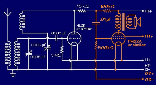
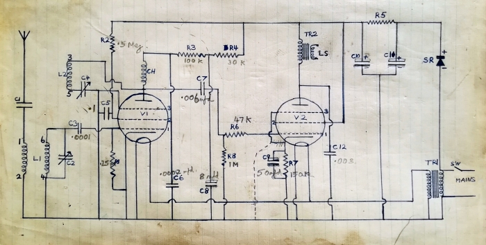
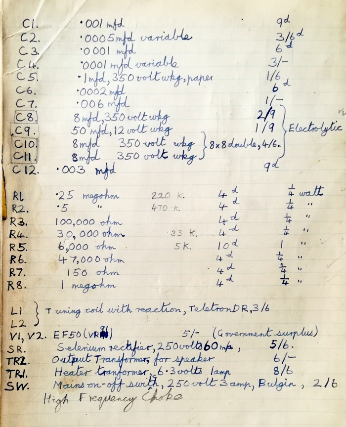
John Shepherd's copies of the    
circuit and components list for the    
Midget AC Mains 2-Valver    

Reproduced by kind permission.    

John Shepherd's circuit, copied from
the BOP details he sent for.
The components list, copied from
the BOP details.
Although John no longer has the set itself, his images (with his schoolboy handwriting and the discoloration of age) are well worth sharing, and it is instructive to compare them with the later version from Fun with Radio.

John also kindly sent me an extract from his life story that he has written for his sons and grandchildren.   In the following, I quote from this with his permission, and have woven into this the other facts that emerged during our interchanges.

Some time around 1953 Mum and I visited [a Scout friend].   His Dad mentioned that he and his son had built a working crystal set.   I listened to it and was gob-smacked!   There was a BBC programme faintly audible in the headphones.   It was built by a boy, had only about five components, did not need a battery, and IT WORKED!   Radio had always been magic and mysterious to me; when I was small I even imagined that there must be miniature musicians inside - nothing else made sense.

Inspired, John went up to his local library and started studying books to understand more, copying electronic circuits and articles into his diary.   A little later, aged 14, he decided to build the Davey Midget AC Mains 2-valver, and sent for the full details.

A lot of the components for that radio and other projects came from wartime surplus shops up in Lisle Street off Leicester Square, or St Martins Lane behind Trafalgar Square.   Others came from Atlantic Radio at Brixton.

[At first m]y radio did not work.   Part of the problem was that my soldering iron was not electric.   It had to be heated in the fire to what I could only guess was the right temperature.   Some of the joints must have been very dodgy.   The iron had a wooden handle and cost 1/6d (7 1/2p) from Woolworths.   Fortunately a neighbour, Mr. Foster, who lived up the Road was a radio amateur and constructor.   He was a postman by day, but in his spare time constructed working television and radio sets using government surplus radar tubes and electronic chassis.   The ex-radar tubes produced a curious green TV picture. He got my radio working and gave me many useful tips.   I am eternally grateful to that man for his patience and guidance.

I now realise how potentially dangerous it was.   There was no earth wire, or mains transformer to isolate the chassis.   Instead, one side of the 240 volt mains was connected directly to the metalwork.   Sometimes I felt a tingling sensation when touching exposed metal parts.   That was the cue to reverse the two-pin plug in the socket to prevent the chassis from being live.   I am fortunate to be here to write about it.


Dangerous or not, John built a second set for a neighbour.   The "live chassis" arrangement was not unusual at the time, and a number of Davey designs used it.   In this case Davey carefully listed the precautions to be taken: the set should not be handled or adjusted while switched on, should not be earthed, and should be enclosed in a cabinet when complete.   Control knob grub screws should be recessed or covered.

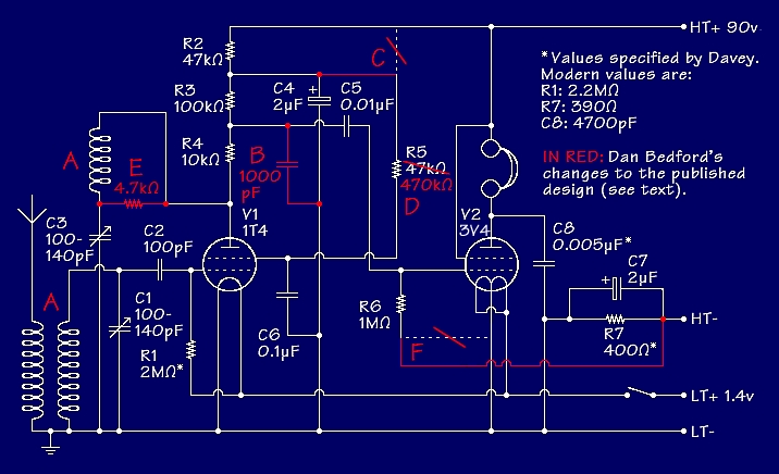
When re-published in Fun with Radio the non-isolated power supply was retained, but the detector valve was strapped as a triode.   In the Fun with Radio version, the audio from the detector is taken from the HT side of the RF choke, whilst John's diagram shows it taken from the detector anode.   I believe that the Fun with Radio version is correct, so either there was an error in the diagrams that BOP sent out on request, or John simply mis-copied it.

Both John's copy and the Fun with Radio version show the output valve's suppressor grid connected to its cathode, but John's copy also shows a dotted connection from the suppressor grid to ground - alongside and apparently superseding this.   Was this perhaps a modification suggested by John's neighbour Mr Foster?

Adding up the prices on the components list, and adding 5 shillings to allow for two EF50s, gives a total of £2 19s 8d (£2.98p) if my arithmetic is correct.   John might have had to add the cost of the High Frequency Choke (un-priced) and a loudspeaker (not mentioned), plus sundries such as chassis materials, wire, screws, and that 2-pin mains plug.   These might have added another £1 10s or so to the budget.   Oh, for a time machine to stock up on cheap old components - but thank goodness for decimal currency!

As mentioned, we have no pictures of this set - unless John decides to do a rebuild, perhaps with a fully isolated power supply!   Although the specified coil is now very scarce, there are others available, and still plenty of EF50s around, so how about it, John?

As mentioned, this design employs a non-isolated power supply, which does not meet modern safety standards.   If you contemplate building a version of this set, please read the warning notice at the head of this page.
 

13: Memories of an
"incognito" BBC Focus set,
and a rebuild
Lewis Thomas's workmanlike    
Focus receiver    

Reproduced by kind permission.    

Lewis Thomas's Focus receiver.


Lewis Thomas writes:
When I was 8 years old I was given the 1965 Boy's Own Annual; it included the BOP Ether Ranger radio by Gilbert Davey.   I always thought I would like to build one, but never did.   I built my first radio by copying a friend's set - we had no circuit diagram nor any information as to who had built it.

I recently came across a copy of the Annual in a second-hand bookshop (I may still have my old copy somewhere) and was taken back in time when I read about the Ether Ranger.   I was interested to find out more about Gilbert Davey, and that is when I found your web site.   It was when I found and read the Focus leaflet that I recognised the circuit as that of the radio that I had built some 50 years before.   I checked with my friend Martin who had the original, and he agreed that it must be the same radio - unfortunately Martin no longer has his radio to compare.   I have recently built a copy of my original Focus, using many of the original parts - my construction skills have improved a bit over 50 years!

I remember that the
[original] radio worked surprisingly well but the selectivity was not so good, and this one is very similar.   The original radio was powered by a 9V battery, and so is the latest version.   However, there is a lot of white noise (probably the old OC71 transistors), this was reduced by using 3V (2x AA cells) with little loss in audio volume.

Lewis has mounted most of the components on stripboard, and housed the receiver in a small aluminium project box, which makes a very workmanlike unit.   As I did, he has added emitter resistors and bypass capacitors - see The Focus Transistor Set.   So it's the Ether Ranger next, is it, Lewis?
 

14: A re-creation of a Davey
short-waver built in the 1960s
Ged Whitney's short-wave set    
on foil-covered wooden chassis    

Reproduced by kind permission.    

Ged Whitney's short-wave set


Ged Whitney writes:
Attached are pictures of a "repro" version I knocked up a few years ago, when I found a copy of Fun with Short Waves at a rally.   It took me back to my first one-valve effort built with my father in about 1969.   I got the book at that time from the local library, and scrounged the parts from local TV shops, the surplus shops of Manchester back then, or those "unofficial" dumps you used to find alongside the canal or a farmer's field . . .

I decided to try my best from memory and reproduce my version.   The chassis is bigger than Davey's measurements, but so was the one I built as a lad - I think I might have got the dimensions wrong at the time.


Ged's set is based upon one of those detailed in Chapter 3 of Fun with Short Waves, 1st edition, 1960.   (Similar designs appeared in Chapter 4 of both the second and third editions - 1968 and 1979.)   It uses the split-floor chassis as made famous by the Studio ‘E’ set, but a good deal larger and covered with foil to minimise hand-capacity effects.   The valve is an EBC33 (double diode triode, diodes unused) as specified by Davey, but that in Ged's present set is missing its metallised coating.   Whilst Davey suggested that the 6.3-volt heater could be powered by a 6-volt "lantern" battery, Ged now uses a mains power supply providing 50 or 100 volts HT and 6.3 volts DC.

With a decent bit of wire, it works fairly well with either HT setting.   As can be seen, the component count is very economical.   I might change that tuning coil; the range has nothing on it really interesting, mostly noises and only a French-speaking broadcast station at the extreme end.   I haven't tested out what the frequency range is - the coil was in the junk box.

If I get the urge to build another one of these (probably better!) I'll forward you the details . . .


My thanks to Ged for sending me his pictures.   Ged's set has whetted my appetite to build a Davey short-waver for my next project!
 

15: Hugh Castellan's
BOP 1948 2-valver
Hugh Castellan's    
1948 2-valver:    
Front, side and rear views.    

Photographed by site author    
with kind permission.


Hugh's 1948 2-valver,
front view.
Hugh's 1948 2-valver,
right-hand view.
Hugh's 1948 2-valver,
rear view.
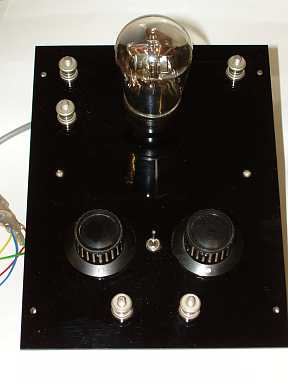
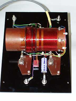
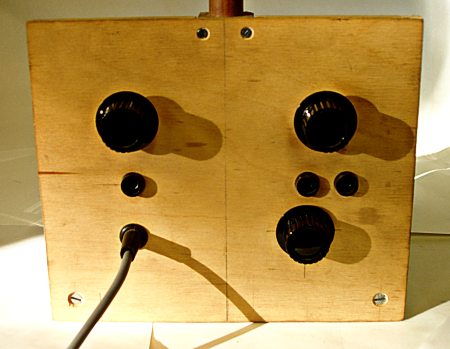
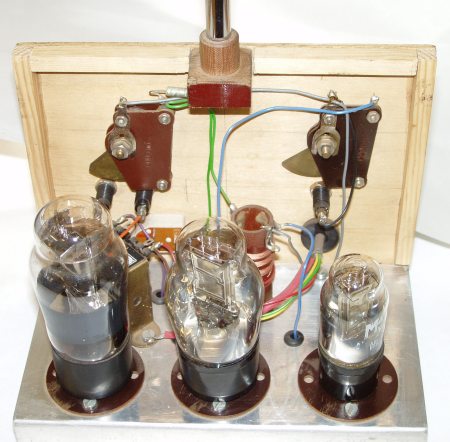
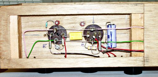
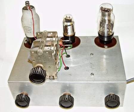
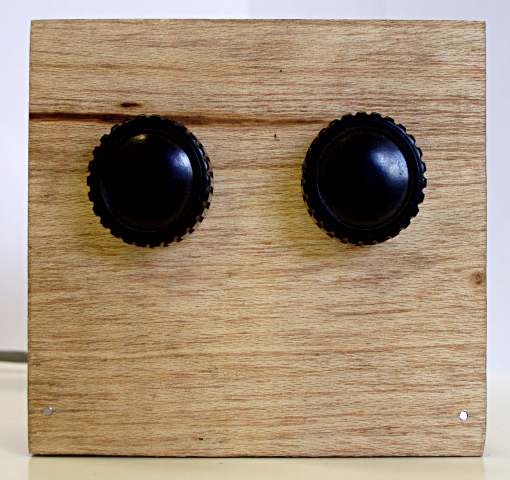
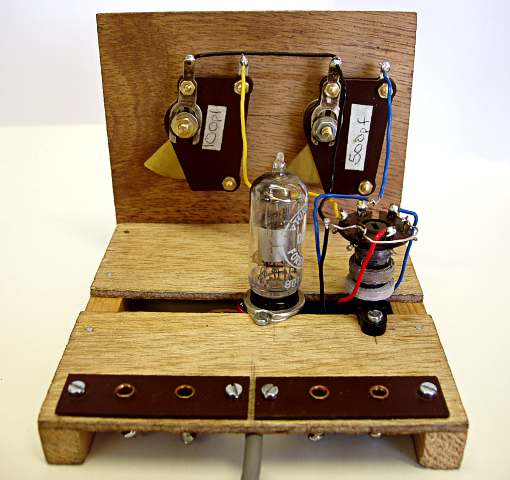
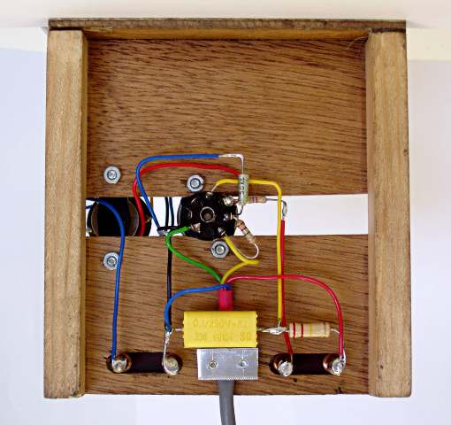
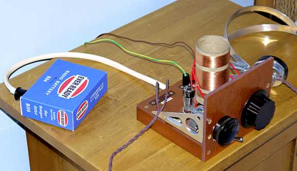
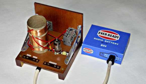
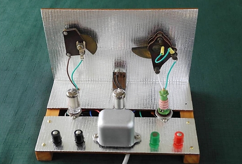
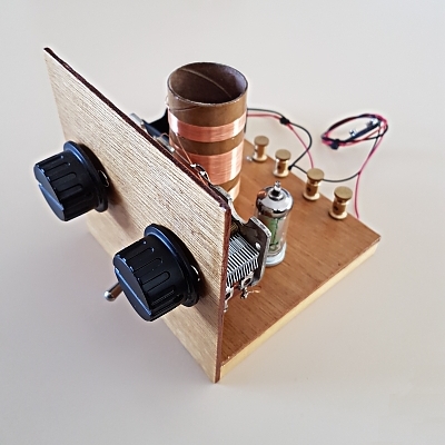
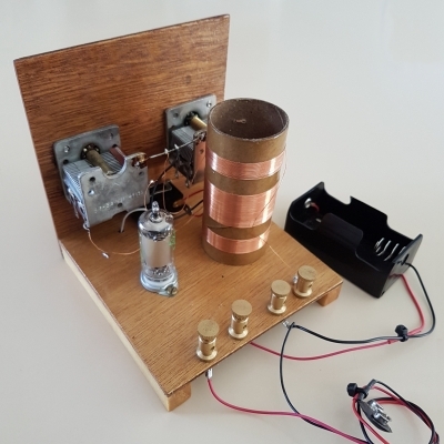
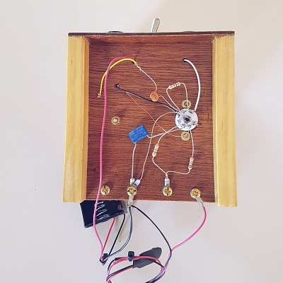
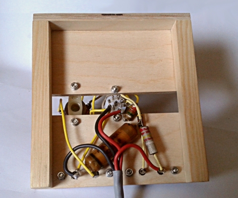
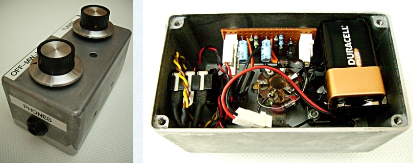
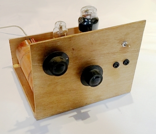
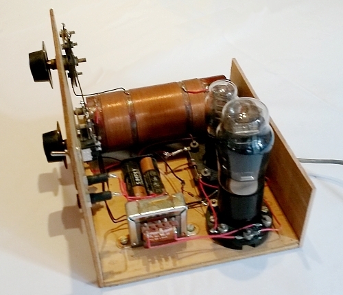
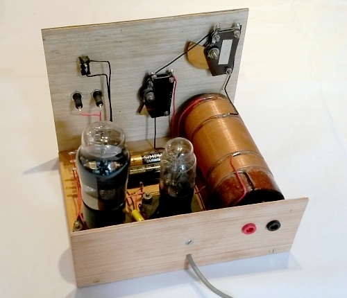
  I am delighted to be able to include another receiver built by Hugh Castellan.   This medium-wave set is based upon the article in the November 1948 edition of Boy's Own Paper, which describes the addition of an output valve to the one-valver 
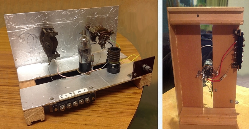
of the February 1948 edition.   The February article had specified construction 
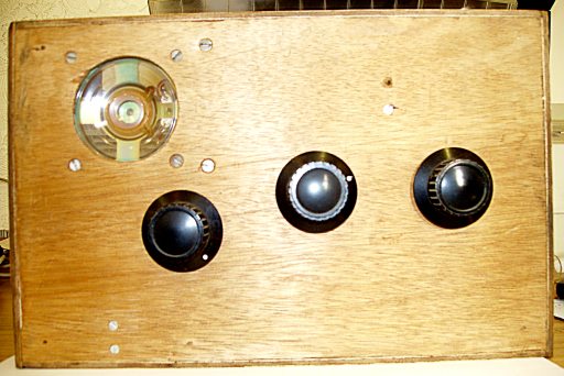
with a plywood front panel and solid baseboard, with a surface-mounted valveholder and space reserved for the second valveholder.

An earlier one-valve set built by Hugh, whilst inspired by the February article, did not follow the construction as depicted there (see item 1 on this page).

In Hugh's latest set, construction does closely follow the article.   The homebrew coil has aerial, tuning (medium wave) and reaction windings.   The valves are the 2-volt types specified by Davey: HL2K detector, and PM22A pentode output valve.

Hugh has found room on the baseboard for both the grid bias battery (2 x AA cells in holder) and the output tranformer, which were assumed in the article to be housed elsewhere.   The output transformer is the same as used in Hugh's other sets employing the PM22A: Type HC2(A) specially produced for him by Majestic Transformer Company.   The secondary connections are led to sockets on the front panel.

As Hugh does not like long unsupported wiring, one or two runs are supported on nails driven into the baseboard.

There are some modern components: as well as the grid bias battery holder and output transformer, fixed capacitors and resistors are to the nearest modern values.

Circuit diagram, with    
output stage in orange.    

Circuit diagram, with
output stage in orange.
The February and November 1948 BOP articles both gave practical layouts, but neither carried circuit diagrams.   From the information given in the November article, I have drawn the complete two-valve circuit, which appears here, with the output stage shown in orange.   Compare it with the one-valve circuit which is given on the THE BEGINNER'S 1-VALVER page.

For the HL2K and PM22A pin connections, and details of the special output transformer, see the PDF download for the Holiday Radio, item 3 above, or that for the Simple Three-Valve Radio, item 4 above.
 

BACK TO TOP
CONTACT ME
I would be delighted to hear about YOUR Davey projects, whether constructed recently or long ago.